
Overview
YOKOGAWA AIP434-S1 Migration-Ready Analog Input Module for Legacy FA-M3 Control Systems
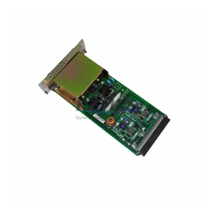
The YOKOGAWA AIP434-S1 is a 4-channel isolated analog input module designed for the FA-M3 programmable controller platform. As legacy FA-M3 installations approach end-of-support milestones, engineering teams managing scheduled outages, emergency replacements, and phased control system upgrades rely on migration-ready stock of the AIP434-S1 to maintain process continuity without forcing a full platform migration. Each unit supplied by KNMKS is pre-tested prior to shipment, covered by a support terms confirmed by quotation, and dispatched from multi-region inventory to support both planned maintenance windows and unplanned downtime events.
The AIP434-S1 accepts 4 channels of isolated analog input signals — typically 4–20 mA or 1–5 V DC depending on range card configuration — and maps them directly to the FA-M3 CPU’s I/O address space via the F3SP-series backplane. When replacing a failed or end-of-life AIP434-S1 in an existing rack, engineers must confirm the slot address assignment in the system definition tool (WideField3 or WideField2), verify that the range card installed in the original module matches the replacement unit’s channel configuration, and check that the analog scaling parameters in the ladder program remain consistent with the new module’s resolution and conversion cycle time. No hardware modification to the backplane or terminal block wiring is required for a direct slot-for-slot replacement, provided the terminal block connector is transferred from the original module.
In retrofit scenarios where the AIP434-S1 is being introduced into a partially upgraded rack alongside newer F3SP71-4N or F3SP76-7N CPU modules, compatibility with the existing F3BU04-0N or F3BU16-0N base units should be confirmed against the FA-M3 system configuration manual. The module communicates over the FA-M3 internal bus and does not require separate communication parameter configuration, which simplifies integration when the rack also contains F3LC11-1F or F3LC12-1F loop control modules sharing the same analog signal infrastructure. Where the control cabinet includes an F3YP04-0P analog output module on adjacent slots, engineers should verify that the combined module power draw does not exceed the base unit’s 5 V DC internal bus capacity — a common oversight during incremental rack expansion projects.
For sites migrating from older AIP434 (non-S1) variants or from third-party analog input cards previously installed in FA-M3-compatible racks, the AIP434-S1’s isolated channel architecture eliminates ground loop interference that frequently affects legacy non-isolated input modules in environments with long cable runs or mixed signal grounding. This makes the AIP434-S1 a preferred replacement in process industries including chemical, oil and gas, water treatment, and power generation, where signal integrity across 4–20 mA loops connected to field transmitters is critical to accurate process variable measurement.
When the replacement is performed during a live system migration rather than a full shutdown, engineers should use WideField3’s online monitoring function to verify that the new module’s channel data registers are updating correctly before transferring control authority back to the CPU. HMI screens connected via the FA-M3’s Ethernet or RS-232C communication links — including YOKOGAWA’s own FAST/TOOLS SCADA or third-party HMI panels using Modbus TCP or MELSEC protocol drivers — should be validated against the new module’s I/O tag mapping to confirm that analog display values and alarm thresholds remain accurate after the swap.
Migration Compatibility Table
| Parameter | Detail |
|---|---|
| SKU | AIP434-S1 |
| Brand / Series | YOKOGAWA FA-M3 |
| Module Type | 4-Channel Isolated Analog Input |
| Signal Range | 4–20 mA / 1–5 V DC (range card dependent) |
| Channel Isolation | Channel-to-channel isolated |
| Compatible Base Units | F3BU04-0N, F3BU16-0N, F3BU32-0N |
| Compatible CPUs | F3SP22-0S, F3SP28-3N, F3SP38-6N, F3SP53-4H, F3SP58-6H, F3SP71-4N, F3SP76-7N |
| Backplane Interface | FA-M3 internal bus (slot-based, no external wiring) |
| Terminal Block | Removable screw terminal (transfer from original module) |
| Programming Tool | WideField3 / WideField2 (system definition + I/O assignment) |
| Slot Address Config | Required — verify in system definition before power-on |
| Firmware Compatibility | Compatible with FA-M3 CPU firmware R9.xx and above; verify for older revisions |
| Direct Replacement For | AIP434 (non-S1), legacy non-isolated analog input modules in FA-M3 racks |
| Installation Space | Standard FA-M3 single slot |
| Pre-Shipment Testing | Yes — functional test on FA-M3 rack prior to dispatch |
| Support terms | 12 months from date of shipment |
| Lead Time | availability confirmed by RFQ — same-day or next-business-day dispatch available |
| Origin | Japan |
Retrofit Planning for Existing FA-M3 Automation Systems
A successful AIP434-S1 retrofit begins with a rack audit. Before ordering, confirm the number of occupied slots in the target F3BU04-0N or F3BU16-0N base unit, the current slot address of the failed or end-of-life module, and whether the rack also contains power-intensive modules such as the F3PU20-0S pulse input module or F3YP04-0P analog output module that may affect the 5 V bus budget. In multi-rack configurations connected via the FA-M3’s F3LP01-0N or F3LP02-0N link processor modules, the slot address of the AIP434-S1 must be consistent with the I/O map defined in the master CPU’s system definition — a mismatch will cause the CPU to flag an I/O configuration error on startup.
For sites that have already partially migrated to newer FA-M3 CPU variants such as the F3SP76-7N, the AIP434-S1 remains fully compatible and can coexist in the same rack with newer high-speed I/O modules. Engineers planning a phased migration — where the CPU is upgraded first and analog I/O modules are replaced in subsequent maintenance windows — can retain the AIP434-S1 in service during the CPU upgrade without modification, provided the WideField3 project file is updated to reflect the new CPU type and re-downloaded to the controller. Signal isolators or loop-powered barriers installed upstream of the AIP434-S1’s terminal block should also be inspected during the retrofit to ensure they remain within specification for the replacement module’s input impedance.
Where the control cabinet includes an F3EM01-0N Ethernet communication module or an F3LC11-1F loop controller sharing the same rack, the AIP434-S1’s replacement should be coordinated with the site’s DCS or SCADA team to temporarily suppress analog input alarms in FAST/TOOLS or the connected HMI during the swap window, preventing nuisance trips or false process shutdowns. Programming cables such as the KM11-1 or USB-to-RS-232C adapters used with WideField3 should be on-site and tested before the maintenance window begins.
Downtime Control During FA-M3 System Migration
Minimizing downtime during an AIP434-S1 replacement requires preparation at three levels: program backup, signal isolation, and post-swap verification. Before removing the original module, use WideField3 to perform a full program upload from the CPU and save the project file with a timestamped revision label. This protects the existing ladder logic, system definition, and I/O parameter settings in the event that the CPU requires a re-download after the module swap.
At the field level, the 4–20 mA loops connected to the AIP434-S1’s terminal block should be placed in manual mode at the transmitter or DCS level before the terminal block is disconnected. This prevents open-circuit fault signals from propagating to the CPU’s analog data registers and triggering downstream control actions or safety interlocks. If the process cannot be placed in manual mode, a temporary signal simulator can be connected to the terminal block to hold the analog input values at their last known good state during the swap.
After installing the replacement AIP434-S1 and reconnecting the terminal block, power the rack and use WideField3’s online monitor to confirm that all 4 channels are reading within expected engineering unit ranges before releasing the process back to automatic control. Verify that the HMI analog displays — whether connected via Ethernet, RS-232C, or a third-party Modbus TCP driver — are updating correctly and that no I/O error flags are active in the CPU’s diagnostic registers. Total swap time for a prepared team with a pre-tested replacement module is typically 15–45 minutes, depending on rack accessibility and the number of field signal loops requiring manual mode transitions.
Retrofit Support FAQ
Q1: Is the AIP434-S1 a direct drop-in replacement for the original AIP434 (non-S1)?
Yes. The AIP434-S1 occupies the same single slot in any FA-M3 base unit and uses the same terminal block connector as the original AIP434. The primary difference is the addition of channel-to-channel isolation in the S1 variant, which improves signal integrity in electrically noisy environments. No changes to the ladder program or system definition are required for a slot-for-slot replacement, provided the range card configuration matches the original module.
Q2: What pre-shipment testing is performed on each AIP434-S1 unit?
Each AIP434-S1 supplied by KNMKS is functionally tested on a live FA-M3 rack prior to dispatch. Testing includes channel-by-channel analog input verification across the rated signal range, isolation integrity check, and confirmation that the module is recognized correctly by the FA-M3 CPU in the system definition. A test report is available on request. All units are covered by a support terms confirmed by quotation from the date of shipment.
Q3: Can the AIP434-S1 be used in a rack that also contains newer FA-M3 modules such as the F3SP76-7N CPU?
Yes. The AIP434-S1 is compatible with all FA-M3 CPU variants including the latest F3SP76-7N and F3SP71-4N. It communicates over the FA-M3 internal bus and does not require firmware updates or special configuration when used alongside newer CPU or communication modules. Confirm the slot address assignment in WideField3 after any CPU upgrade to ensure the I/O map remains consistent.
Q4: What is the typical lead time and do you hold stock for emergency replacements?
KNMKS maintains multi-region inventory of the AIP434-S1 to support both planned maintenance and emergency replacement scenarios. In-stock units are available for same-day or next-business-day dispatch. For sites with critical uptime requirements, we recommend confirming stock availability and reserving units in advance of scheduled outages. Contact admin@knmks.com or +86 18359268345 for current stock levels and expedited shipping options.
© 2026 KNMKS. All rights reserved.
Original Source: https://knmks.com
Contact: admin@knmks.com | +86 18359268345
Product Identification
- Brand / Ecosystem
-
YOKOGAWA
Assorted Brands - Model / Series
-
AIP434-S1
Assorted Series - Product Family
- PLCs & Controllers
- Availability Status
- Available on request after model and quantity confirmation
- Inquiry Type
- B2B RFQ, replacement inquiry and project spare-part request
- Pre-Quote Check
- Exact SKU, brand, series, quantity, nameplate photos and destination country are checked before quotation
System Path
Where this product fits in the KNMKS automation structure.
Specification & Inquiry Focus
- Control platform
- PLC, PAC and modular controllers
- Common needs
- CPU, rack, power and I/O expansion
- Project support
- Replacement, cabinet build and maintenance
Buyer Confirmation
Information KNMKS checks before replying.
- Exact model
- AIP434-S1
- Brand / ecosystem
- YOKOGAWA
- Product family
- PLCs & Controllers
- Application note
- Replacement, maintenance, project build or spare-part list
- Useful photos
- Nameplate, installed unit, cabinet layout or connector side
- Delivery details
- Quantity, destination country and target schedule
Document Support
Files and notes can be confirmed during quotation.
- Product photos or nameplate confirmation when available
- Packing and delivery notes before quotation confirmation
- Support scope and delivery terms confirmed per inquiry
- Export document coordination for qualified B2B requests
Inquiry Support
- Model cross-checking before quotation
- CPU, power, rack and expansion module matching
- Support for replacement and project inquiry
What to Send Us
- Brand and exact model number: YOKOGAWA AIP434-S1
- Quantity and required delivery time
- Application, replacement requirement or nameplate photo
- Destination country and shipping preference
RFQ Preparation
This is a product inquiry page built for RFQ communication.
Fast Model Check
Send this model to KNMKS for confirmation.
Include quantity, destination country and photos if this is a maintenance replacement. The inquiry will be saved with a reference number after submission.
Brand & Compatibility Note
KNMKS displays automation product information for well-known industrial brand ecosystems and compatible replacement references. Brand names are used for product identification and compatibility reference only; final availability and commercial terms are confirmed per quotation.
 Manufacturing
 Machine Tools
 Packaging
 Energy & Power
 HMI & Displays
 Servo Systems
 Variable Frequency Drives
 Sensors