
Overview
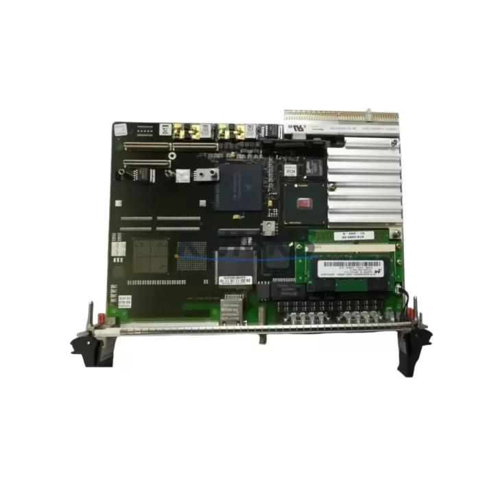
Tektronix G35SB080 671-5612-06 Migration-Ready PSU Board for Legacy Control Systems
The Tektronix G35SB080 671-5612-06 is a migration-ready power supply control board engineered for direct replacement in legacy Tektronix oscilloscope platforms and associated test and measurement control systems. As original Tektronix PSU boards reach end-of-life and factory support is discontinued, maintenance engineers and system integrators face increasing pressure to source verified, drop-in compatible replacements that preserve existing wiring harnesses, backplane connections, and calibration states. The G35SB080 671-5612-06 addresses this challenge by offering a fully tested, specification-matched board that eliminates the need for chassis modification or firmware re-flashing in most standard retrofit scenarios.
When planning a PSU board replacement in a legacy Tektronix instrument, engineers must confirm several critical parameters before committing to a swap. Input voltage range compatibility — typically 100–240 VAC, 50/60 Hz — must be verified against the host chassis power inlet specification. Output rail voltages (commonly ±5 V, ±12 V, and +15 V depending on the oscilloscope model family) must match the downstream analog front-end and timebase board requirements. Connector pinout and harness routing must be confirmed against the original 671-5612-06 assembly drawing to avoid reverse-polarity faults during initial power-on. Physical envelope dimensions, including PCB standoff hole positions and height clearance above the chassis floor, must be measured before installation to ensure the replacement board seats correctly without mechanical interference with adjacent assemblies such as the vertical amplifier board or the trigger circuit module.
In broader system upgrade contexts, the G35SB080 671-5612-06 is frequently deployed alongside other Tektronix legacy components. Technicians performing a full instrument restoration often source the Tektronix 671-4765-00 display driver board and the 671-3893-00 timebase reference assembly in the same procurement cycle, since PSU degradation in aging instruments typically correlates with capacitor aging across multiple sub-assemblies. Where the oscilloscope is integrated into a semi-automated test station controlled by a GPIB interface, the Tektronix GPIB interface board (such as the 671-2455-00 series) must also be inspected for contact oxidation and re-seated after the PSU swap to restore reliable bus communication. In rack-mounted configurations, the power distribution harness connecting the PSU board to the rear-panel binding posts and the front-panel LED indicator circuit should be continuity-tested before the replacement board is energized.
For facilities managing a fleet of legacy Tektronix instruments — including 2465, 2467, 2445, and 2430 series oscilloscopes — a structured spare parts lifecycle plan is essential. The G35SB080 671-5612-06 PSU board is a high-priority stocking item given its role as the primary power source for all downstream analog and digital circuits. Procurement teams should maintain at least one cold-spare unit per instrument cluster to support rapid swap-out during unplanned downtime events. Pre-shipment functional testing, including output voltage verification under load and ripple measurement at each output rail, is performed on every unit prior to dispatch, ensuring that the replacement board arrives in a known-good state and can be installed with confidence during a scheduled or emergency maintenance window.
Migration Compatibility Table
| Parameter | Detail |
|---|---|
| SKU / Part Number | G35SB080 / 671-5612-06 |
| Brand | Tektronix |
| Compatible Platforms | Tektronix 2465, 2467, 2445, 2430 Series Oscilloscopes |
| Function | Power Supply Control Board (PSU) |
| Input Voltage | 100–240 VAC, 50/60 Hz (universal input, verify per chassis label) |
| Output Rails | ±5 V, ±12 V, +15 V (model-dependent; verify against host chassis BOM) |
| Connector Interface | OEM-matched harness connectors; no adapter required for direct replacement |
| PCB Form Factor | Drop-in replacement; confirm standoff positions before installation |
| Firmware / Calibration | No firmware re-flash required; post-installation output voltage trim recommended |
| Communication Protocol | N/A (PSU board; GPIB interface board separate) |
| Pre-shipment Testing | Output voltage verification under load; ripple measurement at all rails |
| Support terms | 12 Months from date of shipment |
| Replacement Recommendation | Direct drop-in for OEM 671-5612-06; inspect harness and standoffs before installation |
| Commissioning Notes | Verify output rails with DMM before reconnecting downstream boards; trim pots accessible via top cover |
Retrofit Planning for Existing Automation Systems
A successful G35SB080 671-5612-06 retrofit begins with a structured pre-installation audit of the host instrument. Before removing the failed PSU board, technicians should document the existing harness routing, photograph connector positions, and record the output voltage readings (if the instrument is still partially functional) to establish a baseline for post-installation verification. The vertical amplifier board — typically located adjacent to the PSU in the 2465 and 2467 chassis — should be inspected for secondary damage caused by PSU rail collapse, as overvoltage or undervoltage events on the ±12 V rails can stress the input protection diodes on the amplifier front end.
In test stations where the oscilloscope is integrated with a signal generator, a frequency counter, or a programmable attenuator via a GPIB bus, the GPIB interface board must be disconnected before the PSU swap and re-seated with fresh contact cleaner applied to the edge connector after the new board is installed. This prevents bus contention errors that can appear as intermittent communication failures in automated test sequences. The timebase reference assembly should also be re-calibrated after the PSU replacement, as output voltage tolerance shifts of even ±50 mV on the +15 V rail can introduce timebase drift in high-accuracy measurement applications.
For rack-mounted instrument clusters, the power distribution harness connecting multiple instruments to a shared AC distribution unit should be load-tested after the PSU swap to confirm that the new board does not introduce ground loop currents that could affect adjacent instruments. Signal isolation between the oscilloscope chassis and the rack frame ground should be verified with a milliohm meter. In facilities where the oscilloscope is used for power electronics characterization, the high-voltage probe interface and the differential probe amplifier module should be re-zeroed after the PSU replacement to eliminate offset errors introduced by minor ground potential shifts.
Downtime Control During System Migration
Minimizing downtime during a G35SB080 671-5612-06 PSU board replacement requires advance preparation and a disciplined swap procedure. The recommended approach is to pre-stage the replacement board in the maintenance area, perform a bench-level output voltage verification before bringing it to the instrument, and prepare all required tools — including a calibrated DMM, a non-conductive standoff driver, and a harness extraction tool — before opening the instrument chassis. This reduces the active swap window to under 30 minutes in most cases, limiting production interruption to a single calibration shift.
Where the oscilloscope supports a warm-standby configuration — for example, in a dual-instrument test station where a backup unit can assume measurement duties during the swap — the control program logic should be validated on the standby instrument before the primary unit is taken offline. This ensures that the test sequence continues without interruption and that the program logic does not need to be re-entered after the primary instrument is restored. After the new PSU board is installed and output voltages are confirmed within specification, the instrument should be allowed a 30-minute thermal soak before final calibration verification to ensure that all output rails have stabilized at operating temperature.
Post-installation, a full functional check — including trigger sensitivity verification, bandwidth confirmation at the rated frequency, and GPIB communication test — should be performed and documented before the instrument is returned to service. This documentation serves as the commissioning record for the replacement and supports the support terms confirmed by quotation claim process if any post-installation issues are identified.
Retrofit Support FAQ
Q1: Is the G35SB080 671-5612-06 a direct replacement for the original Tektronix PSU board?
Yes. The G35SB080 671-5612-06 is a specification-matched replacement for the original Tektronix 671-5612-06 PSU board. No chassis modification is required. Confirm harness connector pinout and standoff positions before installation. Output voltage trim is recommended after installation.
Q2: What pre-shipment testing is performed on each unit?
Every G35SB080 671-5612-06 unit undergoes output voltage verification under load and ripple measurement at all output rails before dispatch. A functional test report is available upon request. The support terms confirmed by quotation cover defects in materials and workmanship from the date of shipment.
Q3: Can this board be installed in both 2465 and 2467 series oscilloscopes?
The G35SB080 671-5612-06 is compatible with multiple Tektronix oscilloscope platforms in the 2400 series family. Confirm the host chassis part number and PSU bay dimensions before ordering. Contact our technical team with your chassis serial number for a definitive compatibility confirmation.
Q4: What is the lead time and stock availability?
Units are held in multi-region stock for rapid dispatch. Standard lead time is 3–7 business days for most destinations. Emergency same-day dispatch is available for in-stock units. Contact admin@knmks.com or +86 18359268345 to confirm current inventory and arrange expedited shipping.
© 2026 KNMKS. All rights reserved.
Original Source: https://knmks.com
Contact: admin@knmks.com | +86 18359268345
Product Identification
- Brand / Ecosystem
-
Other Brands
Assorted Brands - Model / Series
-
G35SB080 671-5612-06
Assorted Series - Product Family
- Power Supplies
- Availability Status
- Available on request after model and quantity confirmation
- Inquiry Type
- B2B RFQ, replacement inquiry and project spare-part request
- Pre-Quote Check
- Exact SKU, brand, series, quantity, nameplate photos and destination country are checked before quotation
System Path
Where this product fits in the KNMKS automation structure.
Specification & Inquiry Focus
- Power range
- DIN rail and switching power supplies
- Common needs
- Voltage, current and mounting style
- Project support
- Control cabinet and panel-builder inquiries
Buyer Confirmation
Information KNMKS checks before replying.
- Exact model
- G35SB080 671-5612-06
- Brand / ecosystem
- Other Brands
- Product family
- Power Supplies
- Application note
- Replacement, maintenance, project build or spare-part list
- Useful photos
- Nameplate, installed unit, cabinet layout or connector side
- Delivery details
- Quantity, destination country and target schedule
Document Support
Files and notes can be confirmed during quotation.
- Product photos or nameplate confirmation when available
- Packing and delivery notes before quotation confirmation
- Support scope and delivery terms confirmed per inquiry
- Export document coordination for qualified B2B requests
Inquiry Support
- 24VDC and cabinet power selection support
- Stable power support for PLC and HMI systems
- Batch inquiry support for panel builders
What to Send Us
- Brand and exact model number: Other Brands G35SB080 671-5612-06
- Quantity and required delivery time
- Application, replacement requirement or nameplate photo
- Destination country and shipping preference
RFQ Preparation
This is a product inquiry page built for RFQ communication.
Fast Model Check
Send this model to KNMKS for confirmation.
Include quantity, destination country and photos if this is a maintenance replacement. The inquiry will be saved with a reference number after submission.
Brand & Compatibility Note
KNMKS displays automation product information for well-known industrial brand ecosystems and compatible replacement references. Brand names are used for product identification and compatibility reference only; final availability and commercial terms are confirmed per quotation.
 Manufacturing
 Machine Tools
 Packaging
 Energy & Power
 PLCs & Controllers
 HMI & Displays
 Servo Systems
 Variable Frequency Drives