
Overview
Siemens ROBICON F7E1A6G2 A1A0100275 Migration-Ready MV Drive Cell: Legacy System Retrofit & Compatibility Upgrade
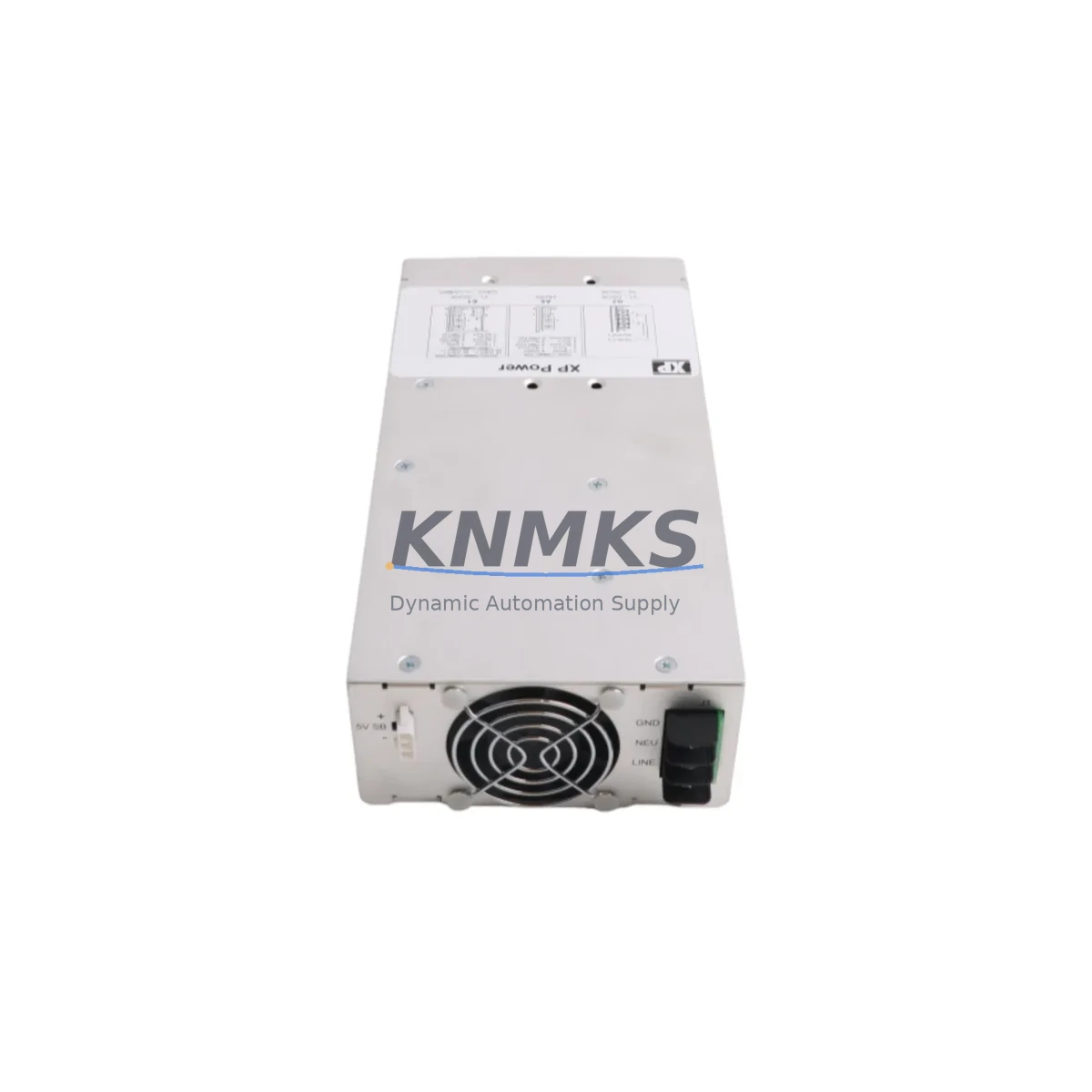
The Siemens ROBICON F7E1A6G2 A1A0100275 is a medium voltage (MV) power cell module engineered for the Perfect Harmony NXG and NXGpro series variable frequency drive (VFD) platforms. As aging Perfect Harmony installations approach end-of-support milestones, this cell provides a verified drop-in replacement path that preserves existing cabinet architecture, fiber-optic gate drive wiring, and NXG controller logic — eliminating the need for full drive replacement and the associated capital expenditure and extended downtime.
For facilities operating legacy ROBICON Perfect Harmony systems in pump, fan, compressor, or extruder applications, the F7E1A6G2 A1A0100275 cell addresses the most critical retrofit constraint: maintaining electrical and mechanical interchangeability with the original cell bay. The module retains the standard cell frame dimensions, DC bus capacitor bank layout, and fiber-optic communication interface compatible with the NXG and NXGpro master controller boards. Engineers planning a cell-level swap should confirm the output voltage rating, cell count per phase, and bypass contactor configuration against the original drive nameplate before dispatch.
Each unit is pre-shipment tested under load conditions, covering gate drive firing sequence, capacitor charge/discharge cycle, thermal sensor output, and fiber-optic link integrity. A support terms confirmed by quotation is included from the date of shipment, covering manufacturing defects and component failure under normal operating conditions. Stock is maintained for immediate dispatch to minimize unplanned downtime windows.
Migration Compatibility Table
| Parameter | Detail |
|---|---|
| SKU / Part Number | ROBICON F7E1A6G2 A1A0100275 |
| Compatible Platform | Siemens Perfect Harmony NXG, NXGpro |
| Cell Frame Compatibility | Drop-in replacement; standard ROBICON cell bay dimensions |
| Communication Interface | Fiber-optic gate drive link (NXG master controller compatible) |
| DC Bus Architecture | Series cell topology; capacitor bank layout preserved |
| Bypass Contactor | Verify bypass contactor rating against original cell specification |
| Cooling Method | Forced air / liquid-cooled variant — confirm cabinet cooling type |
| Installation Space | Confirm cell bay slot dimensions and door clearance before installation |
| Firmware Compatibility | Compatible with NXG firmware revisions; verify controller firmware version |
| Commissioning Requirement | Cell address assignment via NXG HMI; re-run auto-tune if motor parameters changed |
| Pre-Shipment Test | Gate drive, capacitor cycle, thermal sensor, fiber-optic link — all verified |
| Support terms | 12 months from shipment date |
| Origin | Germany (DE) |
| Weight | 2,180 g |
Retrofit Planning for Existing Automation Systems
A successful Perfect Harmony cell replacement requires a structured pre-outage checklist that extends beyond the cell module itself. Before the maintenance window opens, the site engineer should retrieve the NXG controller configuration backup from the NXG HMI panel — typically a Siemens TP1500 or equivalent operator panel — and confirm that the drive parameter set, motor nameplate data, and process PID setpoints are saved to a USB archive. This protects against configuration loss if the NXG master controller board requires reseating or replacement during the same outage.
The fiber-optic harness connecting the NXG master board to each cell’s gate drive board should be inspected for bend radius violations and connector contamination before the new F7E1A6G2 A1A0100275 cell is installed. Damaged fiber links are a common cause of cell communication faults (F-fault codes) after replacement and are frequently overlooked during rapid swap operations. Spare fiber-optic patch cables compatible with the NXG harness assembly should be staged on-site.
For sites where the Perfect Harmony cabinet shares a common MCC lineup with other Siemens SINAMICS or MICROMASTER 440 drives, the upstream MV switchgear interlock logic should be reviewed to confirm that the cell replacement outage does not inadvertently affect adjacent drive feeders. The NXG controller’s cell bypass module — if installed — should be tested for correct bypass contactor operation before the replacement cell is energized.
I/O wiring to the NXG analog input/output board and the digital I/O terminal strip should be documented with a point-to-point wiring diagram before any terminal work begins. If the site uses a Siemens S7-300 or S7-400 PLC for process sequencing, the PROFIBUS DP or PROFINET link to the NXG drive should be verified for correct node address and baud rate settings after the cell swap, as a controller reboot can reset communication parameters to factory defaults on some firmware versions.
Sites upgrading from older Perfect Harmony GH180 or earlier ROBICON cell generations to the NXG platform should also plan for HMI screen migration — existing operator graphics referencing legacy drive fault codes may require remapping to NXG fault nomenclature. The NXG HMI faceplate and the associated SCADA tag list should be updated as part of the retrofit scope to avoid alarm management gaps during the first weeks of post-retrofit operation.
Downtime Control During System Migration
Minimizing production impact during a Perfect Harmony cell replacement depends on three factors: pre-staging, configuration preservation, and a structured energization sequence. The F7E1A6G2 A1A0100275 cell should arrive on-site at least 24 hours before the planned outage window to allow visual inspection, packaging damage assessment, and ambient temperature equalization — particularly important in high-humidity or cold-climate facilities where condensation on capacitor banks can cause insulation resistance failures at first energization.
The NXG controller retains the drive parameter set in non-volatile memory, so a cell-only swap does not require a full parameter re-entry. However, the NXG auto-identification routine should be re-run after cell replacement to update the cell count and voltage rating registers. This routine typically completes in under five minutes and does not require motor rotation, allowing it to be performed with the process load disconnected.
For critical continuous-process applications — such as boiler feed pumps, cooling water circulation, or kiln drives — a cold standby cell strategy is recommended: maintaining one spare F7E1A6G2 A1A0100275 cell on-site reduces the mean time to repair (MTTR) from days to hours. Combined with a pre-tested cell and a documented swap procedure, this approach supports a target outage window of under four hours for a single-cell replacement on a standard three-phase Perfect Harmony NXG cabinet.
After energization, the NXG fault log should be cleared and the drive run at reduced speed (10–20% of rated) for a minimum of 30 minutes before returning to full process load. This burn-in period confirms thermal stability of the new cell and validates fiber-optic link integrity under operating temperature conditions. All observations should be logged in the site maintenance record to support the support terms confirmed by quotation claim process if required.
Retrofit Support FAQ
Q1: Is the ROBICON F7E1A6G2 A1A0100275 a direct replacement for all Perfect Harmony NXG cell positions?
The F7E1A6G2 A1A0100275 is designed for specific cell positions within the Perfect Harmony NXG and NXGpro series. Cell position compatibility depends on the drive’s output voltage rating and the number of cells per phase. Always cross-reference the original drive nameplate, the cell bay label, and the NXG configuration file before ordering. Our technical team can assist with cross-referencing if the original part number is unavailable.
Q2: What commissioning steps are required after installing the replacement cell?
After mechanical installation and fiber-optic reconnection, the NXG controller must recognize the new cell via its auto-identification routine. The cell address is assigned automatically by the NXG master board based on bay position. If the NXG HMI displays a cell communication fault after installation, inspect the fiber-optic connectors for contamination and verify the harness routing. A parameter backup restore may be required if the NXG controller was powered down for an extended period.
Q3: How is the unit tested before shipment, and what does the support terms confirmed by quotation cover?
Each F7E1A6G2 A1A0100275 unit undergoes pre-shipment testing covering gate drive firing sequence, capacitor charge/discharge cycle, thermal sensor output verification, and fiber-optic communication link integrity. The support terms confirmed by quotation cover manufacturing defects and component failure under normal operating conditions from the date of shipment. Support requests require the original invoice and a fault description; physical damage caused by incorrect installation or overvoltage events is excluded.
Q4: What is the typical lead time, and do you maintain stock for emergency orders?
Stock is maintained for immediate dispatch. Standard orders ship within 1–2 business days. For emergency breakdown situations, contact our sales team directly to confirm real-time availability and expedited freight options. We support global shipment to North America, Europe, and Asia-Pacific with appropriate export documentation.
© 2026 KNMKS. All rights reserved.
Original Source: https://knmks.com
Contact: admin@knmks.com | +86 18359268345
Product Identification
- Brand / Ecosystem
-
Siemens
Siemens - Model / Series
- ROBICON F7E1A6G2 A1A0100275
- Product Family
- Variable Frequency Drives
- Availability Status
- Available on request after model and quantity confirmation
- Inquiry Type
- B2B RFQ, replacement inquiry and project spare-part request
- Pre-Quote Check
- Exact SKU, brand, series, quantity, nameplate photos and destination country are checked before quotation
System Path
Where this product fits in the KNMKS automation structure.
Specification & Inquiry Focus
- Drive range
- AC drives, VFDs and accessories
- Common needs
- Voltage, kW/HP and load type
- Project support
- Motor control, energy saving and spares
Buyer Confirmation
Information KNMKS checks before replying.
- Exact model
- ROBICON F7E1A6G2 A1A0100275
- Brand / ecosystem
- Siemens
- Product family
- Variable Frequency Drives
- Application note
- Replacement, maintenance, project build or spare-part list
- Useful photos
- Nameplate, installed unit, cabinet layout or connector side
- Delivery details
- Quantity, destination country and target schedule
Document Support
Files and notes can be confirmed during quotation.
- Product photos or nameplate confirmation when available
- Packing and delivery notes before quotation confirmation
- Support scope and delivery terms confirmed per inquiry
- Export document coordination for qualified B2B requests
Inquiry Support
- Input/output voltage and kW/HP confirmation
- Energy-saving motor control inquiry
- Accessory and spare-unit support
What to Send Us
- Brand and exact model number: Siemens ROBICON F7E1A6G2 A1A0100275
- Quantity and required delivery time
- Application, replacement requirement or nameplate photo
- Destination country and shipping preference
RFQ Preparation
This is a product inquiry page built for RFQ communication.
Fast Model Check
Send this model to KNMKS for confirmation.
Include quantity, destination country and photos if this is a maintenance replacement. The inquiry will be saved with a reference number after submission.
Brand & Compatibility Note
KNMKS displays automation product information for well-known industrial brand ecosystems and compatible replacement references. Brand names are used for product identification and compatibility reference only; final availability and commercial terms are confirmed per quotation.
 Manufacturing
 Machine Tools
 Packaging
 Energy & Power
 PLCs & Controllers
 HMI & Displays
 Servo Systems
 Sensors