
Overview
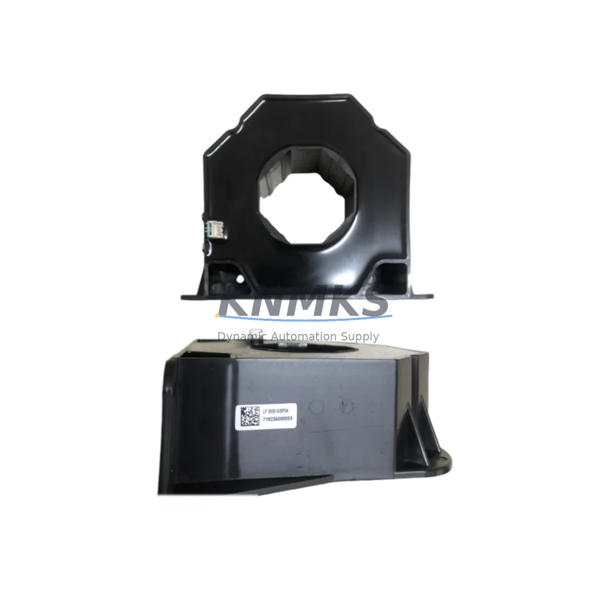
Siemens A5E31867280 LF2005-S/SP34 Migration-Ready CT for Legacy Control Systems
The Siemens A5E31867280 LF2005-S/SP34 is a 2000/5A metering-class current transformer engineered for integration within SENTRON power monitoring and protection systems. As legacy switchgear panels and energy management installations approach end-of-life, this CT serves as a verified retrofit replacement for discontinued or aging measurement components — enabling engineers to restore accurate current sensing without redesigning the entire control cabinet.
In retrofit and upgrade projects, the A5E31867280 is commonly deployed alongside the Siemens SENTRON PAC3200 power monitoring device and the SENTRON 3WL or 3VA series circuit breakers, where precise secondary current input (5A nominal) is critical for protection relay coordination and energy metering accuracy. When replacing an older LF-series CT in an existing panel, engineers must verify the secondary burden rating against the connected measuring instruments — particularly when the downstream device is a Siemens 7KM PAC series meter or a third-party power analyzer with a 5A input class.
Terminal wiring adaptation is a key step during installation. The LF2005-S/SP34 uses standard S1/S2 secondary terminals; if the legacy CT used a different terminal designation (K/L or H1/H2), the field wiring diagram must be updated accordingly before energizing. Failure to short-circuit the secondary before disconnecting the old CT is a common site risk — always confirm that the secondary circuit is closed before any physical swap. The primary conductor routing through the CT window must also be confirmed against the rated primary current (2000A) and the available window aperture in the existing busbar arrangement.
For control cabinet upgrades involving Siemens SIMATIC S7-300 or S7-400 PLCs with analog input modules (such as the SM 331 or SM 334), the CT secondary output feeds into a transducer or directly into the metering bus. Confirm that the analog input channel scaling in the PLC program matches the new CT ratio (2000/5A = 400:1) before going live. If the original program was calibrated to a different CT ratio, a parameter update in the STEP 7 or TIA Portal project is required — this is a common source of post-retrofit measurement error that extends commissioning time.
In systems where the CT feeds a Siemens SICAM RTU or a substation automation gateway, verify that the IEC 61850 or Modbus register mapping for the current channel reflects the updated CT ratio. Communication link continuity — particularly on PROFIBUS DP or PROFINET segments connecting the metering device to the SCADA layer — should be validated after the CT swap to confirm that no address conflicts or timeout faults have been introduced.
Rack space and DIN rail mounting geometry should be confirmed before ordering. The LF2005-S/SP34 is designed for busbar pass-through installation; if the existing panel uses a different busbar cross-section or a non-standard mounting bracket, a mechanical adapter may be required. Document the available installation space, busbar orientation (horizontal/vertical), and proximity to adjacent components before finalizing the retrofit BOM.
Firmware compatibility is not directly applicable to passive CT components, but the downstream metering or protection relay firmware version should be checked against the manufacturer’s compatibility matrix — particularly if the relay was last updated several years ago and the new CT introduces a different accuracy class (e.g., Class 0.5S vs. Class 1). Accuracy class mismatches can trigger calibration warnings or affect billing-grade metering compliance.
All units supplied by KNMKS are pre-shipment tested for ratio accuracy, polarity, and insulation integrity. Stock is maintained across multiple regional warehouses to support urgent retrofit and emergency spare requirements. A support terms confirmed by quotation is provided on all A5E31867280 units, covering manufacturing defects and ratio deviation beyond published tolerance.
Migration Compatibility Table
| Parameter | A5E31867280 LF2005-S/SP34 | Retrofit Notes |
|---|---|---|
| Primary Current | 2000A | Confirm busbar current matches rated primary |
| Secondary Current | 5A | Verify downstream meter/relay input class |
| CT Ratio | 2000/5A (400:1) | Update PLC/relay scaling if ratio changed |
| Secondary Terminals | S1 / S2 | Remap if legacy CT used K/L or H1/H2 labeling |
| Mounting Type | Busbar pass-through | Confirm window aperture and busbar cross-section |
| Accuracy Class | Class 0.5S (metering) | Check relay firmware compatibility with accuracy class |
| Communication Compatibility | Passive CT — feeds metering/relay input | Validate Modbus/IEC 61850 register mapping post-swap |
| Compatible Systems | SENTRON PAC, 3WL, 3VA, SICAM, SIMATIC S7 | Confirm analog input scaling in TIA Portal / STEP 7 |
| Commissioning Focus | Ratio verification, polarity check, burden test | Short-circuit secondary before disconnecting old CT |
| Support terms | 12 Months | Covers ratio deviation and manufacturing defects |
Retrofit Planning for Existing Automation Systems
A successful retrofit begins with a complete audit of the existing panel BOM. For installations built around the Siemens SENTRON PAC3200 or PAC4200 power monitoring units, the CT secondary burden must be calculated against the total connected load — including the meter input impedance, wiring resistance, and any intermediate transducer. Exceeding the rated burden of the LF2005-S/SP34 will degrade accuracy and may cause thermal stress on the secondary winding.
When the retrofit scope extends to replacing the protection relay — for example, upgrading from an older Siemens 7SJ61 overcurrent relay to a 7SJ82 — the CT secondary circuit must be re-evaluated for the new relay’s input impedance and CT requirements. In multi-feeder panels, each feeder CT should be documented individually, as mixed CT ratios on the same busbar section can complicate differential protection schemes.
For I/O expansion projects where a Siemens ET 200SP or ET 200M distributed I/O station is being added to the control architecture, confirm that the analog input module selected for current measurement is rated for 5A AC input — not 4–20mA or 0–10V — to avoid signal conditioning errors. If a signal isolator or transducer (such as a Siemens SITRANS TR200 or equivalent) is used between the CT and the analog input, its output range and scaling must be documented in the PLC program before commissioning.
HMI screen updates are often overlooked during CT replacements. If the existing Siemens SIMATIC HMI TP700 or KTP900 panel displays current values derived from the CT ratio, the tag scaling in the WinCC or TIA Portal HMI project must be updated to reflect the new ratio. Failure to do so results in incorrect current readings on the operator display — a common post-retrofit punch-list item that delays final acceptance.
Downtime Control During System Migration
Minimizing downtime during a CT replacement requires pre-staging all materials and completing as much preparation work as possible while the system is live. Before the scheduled outage window, verify that the replacement A5E31867280 has been ratio-tested and that all terminal labels, wiring diagrams, and PLC parameter changes are documented and approved.
During the outage, follow a strict sequence: isolate the primary circuit, short-circuit the CT secondary terminals, disconnect the old CT wiring (labeling each conductor), remove the old CT, install the A5E31867280, reconnect the secondary wiring, verify polarity with a CT polarity tester, remove the short-circuit link, and restore the primary circuit. This sequence protects both personnel and the downstream metering equipment from open-circuit secondary voltage spikes.
After restoration, perform a live ratio check using a clamp meter on the primary and a calibrated ammeter on the secondary to confirm the 400:1 ratio under load. Cross-check the PLC analog input reading against the clamp meter value to validate the scaling update. If the system includes a Siemens SICAM A8000 RTU or similar substation automation device, confirm that the current channel value is updating correctly in the SCADA system before releasing the panel back to operations.
For critical production environments, consider a parallel commissioning approach: install the new CT on a spare busbar position (if available) and validate its output before switching over. This approach eliminates the risk of extended downtime caused by unexpected wiring or scaling issues discovered only after the old CT has been removed.
Retrofit Support FAQ
Q1: Is the A5E31867280 LF2005-S/SP34 a direct replacement for other LF-series Siemens CTs?
The LF2005-S/SP34 is dimensionally and electrically compatible with other LF-series CTs of the same ratio and burden class. However, always verify the window aperture, secondary burden rating, and accuracy class against the original CT datasheet before substituting. If the original CT was a different ratio (e.g., 1000/5A or 3000/5A), the PLC and relay scaling must be updated accordingly.
Q2: What commissioning checks are required after installation?
Perform a live ratio verification under load, a polarity check, a secondary burden measurement, and a visual inspection of all terminal connections. If the CT feeds a protection relay, conduct a secondary injection test to confirm relay pickup settings. Update and re-validate all PLC analog input scaling and HMI tag values before final sign-off.
Q3: Can this CT be used with non-Siemens metering and protection equipment?
Yes. The A5E31867280 LF2005-S/SP34 outputs a standard 5A secondary current and is compatible with any metering or protection device rated for 5A CT input, regardless of manufacturer. Confirm the secondary burden and accuracy class requirements of the third-party device before installation.
Q4: What does the support terms confirmed by quotation cover, and what is the lead time for in-stock units?
The support terms confirmed by quotation cover manufacturing defects and ratio deviation beyond the published accuracy class tolerance. In-stock units are pre-shipment tested for ratio accuracy, polarity, and insulation integrity. Lead time for in-stock units is typically 3–7 business days for international shipments. Contact admin@knmks.com for current stock availability and expedited shipping options.
© 2026 KNMKS. All rights reserved.
Original Source: https://knmks.com
Contact: admin@knmks.com | +86 18359268345
Product Identification
- Brand / Ecosystem
-
Siemens
Siemens - Model / Series
- A5E31867280 LF2005-S/SP34
- Product Family
- Other Components
- Availability Status
- Available on request after model and quantity confirmation
- Inquiry Type
- B2B RFQ, replacement inquiry and project spare-part request
- Pre-Quote Check
- Exact SKU, brand, series, quantity, nameplate photos and destination country are checked before quotation
System Path
Where this product fits in the KNMKS automation structure.
Specification & Inquiry Focus
- Component range
- Breakers, terminals and cabinet accessories
- Common needs
- Model, photo and installation requirement
- Project support
- Maintenance and mixed spare-part inquiry
Buyer Confirmation
Information KNMKS checks before replying.
- Exact model
- A5E31867280 LF2005-S/SP34
- Brand / ecosystem
- Siemens
- Product family
- Other Components
- Application note
- Replacement, maintenance, project build or spare-part list
- Useful photos
- Nameplate, installed unit, cabinet layout or connector side
- Delivery details
- Quantity, destination country and target schedule
Document Support
Files and notes can be confirmed during quotation.
- Product photos or nameplate confirmation when available
- Packing and delivery notes before quotation confirmation
- Support scope and delivery terms confirmed per inquiry
- Export document coordination for qualified B2B requests
Inquiry Support
- Mixed automation spare parts inquiry
- Cabinet component and accessory support
- Model identification from photos or labels
What to Send Us
- Brand and exact model number: Siemens A5E31867280 LF2005-S/SP34
- Quantity and required delivery time
- Application, replacement requirement or nameplate photo
- Destination country and shipping preference
RFQ Preparation
This is a product inquiry page built for RFQ communication.
Fast Model Check
Send this model to KNMKS for confirmation.
Include quantity, destination country and photos if this is a maintenance replacement. The inquiry will be saved with a reference number after submission.
Brand & Compatibility Note
KNMKS displays automation product information for well-known industrial brand ecosystems and compatible replacement references. Brand names are used for product identification and compatibility reference only; final availability and commercial terms are confirmed per quotation.
 Manufacturing
 Machine Tools
 Packaging
 Energy & Power
 PLCs & Controllers
 HMI & Displays
 Servo Systems
 Variable Frequency Drives