
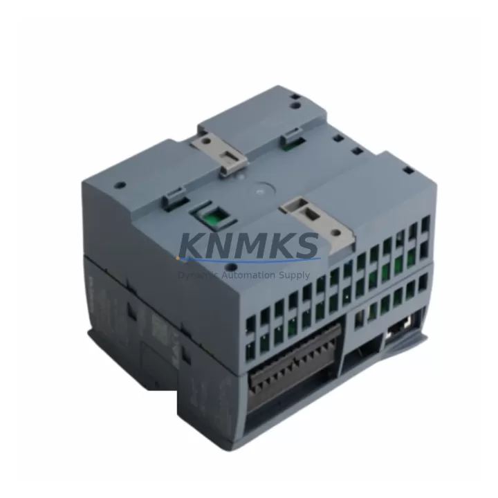
Overview
Schneider TRICONEX 2551 Migration-Ready Termination Panel for Legacy Systems
The TRICONEX 2551 is a field-proven termination panel engineered for Schneider Electric’s Tricon Triple Modular Redundant (TMR) safety system platform. As legacy Tricon installations approach end-of-support milestones, the 2551 serves as a critical interface component in both direct replacement scenarios and phased migration projects — preserving existing field wiring, terminal layouts, and I/O channel assignments without requiring panel re-engineering. For facilities operating aging Tricon chassis with original TRICONEX 3000 or 3006 main processors, the 2551 termination panel eliminates the need to re-terminate hundreds of field cables during a control system upgrade, dramatically reducing both engineering hours and unplanned downtime risk.
In retrofit projects where the primary controller is being migrated from a legacy Tricon TMR rack to a newer Trident or TriStation 1131-compatible architecture, the 2551 panel maintains physical and electrical continuity at the field junction. Engineers can retain existing cable schedules, loop drawings, and marshalling configurations while upgrading the logic solver and communication infrastructure. This approach is particularly valuable in SIL 2 and SIL 3 safety instrumented systems (SIS) where re-validation costs for field wiring changes can exceed the cost of the hardware itself.
When planning a migration involving the TRICONEX 2551, site engineers should verify power supply capacity at the Tricon chassis — particularly when adding TRICONEX 3805E or 3604E I/O modules alongside the existing termination assembly. Backplane slot assignments must be confirmed against the original system configuration report to avoid address conflicts with retained I/O modules. Terminal block wiring should be cross-referenced against the as-built loop drawings before any live cutover, and all field signal types (4–20 mA, discrete 24 VDC, RTD, thermocouple) must be validated against the replacement module’s input specifications.
Communication link integrity is another key checkpoint: if the legacy Tricon system uses TRICONEX Enhanced Intelligent Communication Module (EICM) or a dedicated Modbus/HART gateway, the replacement architecture must maintain protocol continuity to avoid disrupting DCS integration or historian data feeds. HMI screens built on TriStation or third-party SCADA platforms referencing Tricon tag addresses should be audited before cutover to ensure tag mapping remains valid post-migration.
Physical installation space must also be confirmed. The 2551 termination panel is designed for standard Tricon chassis mounting, but when integrating into a modernized control cabinet alongside newer TRICONEX 3008 main processors or updated power modules such as the TRICONEX 8312, rack depth, DIN rail clearance, and cable management routing should be re-evaluated. Firmware compatibility between the termination panel interface and the replacement logic solver should be confirmed with the TriStation 1131 project file version in use on site.
Pre-shipment functional testing is performed on every TRICONEX 2551 unit prior to dispatch. Each panel is verified for terminal continuity, connector seating integrity, and backplane interface alignment. Units are supplied with a support terms confirmed by quotation covering manufacturing defects and functional failures under normal operating conditions, supporting procurement teams that require documented support terms coverage for spare parts lifecycle planning.
Migration Compatibility Table
| Parameter | TRICONEX 2551 Specification | Migration / Retrofit Notes |
|---|---|---|
| Platform Compatibility | Tricon TMR Safety System | Compatible with Tricon v9/v10 chassis; verify slot assignment before installation |
| Termination Type | Field-side terminal block assembly | Retains existing field cable terminations; no re-wiring required in most retrofit scenarios |
| Communication Compatibility | Tricon backplane interface | Confirm EICM or Modbus gateway tag mapping before cutover |
| Safety Rating | SIL 2 / SIL 3 capable (system-level) | Re-validation required if field wiring is modified during migration |
| Installation Requirement | Standard Tricon chassis slot | Verify rack depth and cable clearance when co-installing with TRICONEX 3008 or 8312 |
| Firmware | Compatible with TriStation 1131 | Confirm project file version compatibility before commissioning |
| Replacement Recommendation | Direct drop-in for legacy 2551 installations | Suitable for like-for-like replacement without panel re-engineering |
| Support terms | 12 Months | Covers manufacturing defects and functional failures under normal operating conditions |
Retrofit Planning for Existing Automation Systems
A successful TRICONEX 2551 retrofit begins with a thorough audit of the existing Tricon chassis configuration. In most legacy installations, the 2551 termination panel interfaces directly with TRICONEX 3604E or 3805E digital I/O modules, and the physical terminal layout must be cross-referenced against the current loop drawings before any hardware is disturbed. Where the existing system includes a TRICONEX 3703E analog input module for process variable monitoring, signal type compatibility (mA vs. voltage) must be confirmed at the termination panel level to avoid misconfiguration during the swap.
Power distribution within the control cabinet is a frequent constraint in retrofit projects. When the 2551 is being installed alongside a replacement TRICONEX 3008 main processor or an updated TRICONEX 8312 power module, the total chassis power budget must be recalculated to ensure no slot exceeds the backplane current limit. This is especially relevant in high-density I/O configurations where multiple termination panels share a single power rail.
For sites using a TRICONEX Enhanced Intelligent Communication Module (EICM) to bridge the Tricon system to a DCS or historian, the communication module’s configuration file must be backed up and validated against the replacement architecture before the cutover window opens. If the migration path includes transitioning from a legacy serial Modbus link to an Ethernet-based protocol, a TRICONEX 4351B or equivalent communication gateway may need to be introduced into the panel layout, requiring additional DIN rail space and cable routing planning.
HMI integration is another area requiring pre-migration attention. Facilities running TriStation 1131-based operator interfaces or third-party SCADA systems with hardcoded Tricon tag references must audit all affected displays and alarm configurations before the 2551 replacement is commissioned. Tag address continuity is critical to maintaining alarm management integrity and avoiding nuisance trips during the post-cutover stabilization period.
Downtime Control During System Migration
Minimizing production downtime during a TRICONEX 2551 replacement requires a structured pre-outage preparation protocol. All field terminal identifications should be photographed and cross-referenced against the as-built wiring schedule before any terminals are disturbed. Where the existing installation uses color-coded cable markers or numbered ferrules, these should be preserved or replicated on the replacement assembly to eliminate re-identification errors during recommissioning.
The original TriStation 1131 project file — including all logic blocks, cause-and-effect matrices, and safety function configurations — must be archived and version-controlled before the cutover begins. If the migration involves any changes to I/O module addressing or channel assignments, the updated project file should be compiled, syntax-checked, and loaded onto a bench-test chassis before the live system is touched. This approach protects the integrity of the safety program and allows the commissioning team to verify all output responses before the process is returned to automatic control.
During the physical swap, field signals should be isolated at the marshalling cabinet level where possible, and a temporary bypass or inhibit strategy should be agreed with the process safety team in advance. Post-installation loop checks should cover every channel on the 2551 termination panel, with results documented against the original loop test records. Communication link restoration — including Modbus polling, HART pass-through, and DCS tag synchronization — should be verified before the system is released from maintenance mode. A structured post-cutover monitoring period of 24–72 hours is recommended to confirm stable operation before the bypass strategy is lifted.
Retrofit Support FAQ
Q: Is the TRICONEX 2551 a direct replacement for the original panel in legacy Tricon TMR installations?
A: Yes. The 2551 is designed as a like-for-like replacement for existing Tricon TMR termination panel installations. Terminal layout, backplane connector geometry, and chassis mounting dimensions are consistent with the original specification, allowing direct substitution without panel re-engineering in the majority of retrofit scenarios. Site-specific wiring verification is always recommended before installation.
Q: What commissioning steps are required after installing the TRICONEX 2551?
A: After physical installation, the commissioning sequence should include: (1) terminal continuity verification against the as-built loop drawings, (2) backplane slot address confirmation in the TriStation 1131 project file, (3) channel-by-channel loop test for all connected field instruments, (4) communication link validation (Modbus, HART, or Ethernet as applicable), and (5) functional test of all safety outputs before returning the system to automatic control.
Q: Can the 2551 be used alongside newer TRICONEX modules such as the 3008 main processor or 8312 power module?
A: The 2551 termination panel is compatible with the Tricon TMR backplane architecture used across the Tricon product family. When co-installing with newer modules such as the TRICONEX 3008 or 8312, the chassis power budget and slot assignment plan should be reviewed to confirm compatibility. Firmware version alignment between the main processor and the I/O subsystem should also be verified using the TriStation 1131 project configuration.
Q: What support terms and inventory support is available for the TRICONEX 2551?
A: Every TRICONEX 2551 unit is supplied with a support terms confirmed by quotation covering manufacturing defects and functional failures under normal operating conditions. Pre-shipment functional testing is performed on all units prior to dispatch. Stock availability is maintained to support both planned retrofit projects and emergency spare parts requirements. Contact our team for lead time confirmation and volume pricing.
—
© 2026 KNMKS. All rights reserved.
Original Source: https://knmks.com
Contact: admin@knmks.com | +86 18359268345
Product Identification
- Brand / Ecosystem
-
Schneider
Assorted Brands - Model / Series
-
TRICONEX 2551
Assorted Series - Product Family
- PLCs & Controllers
- Availability Status
- Available on request after model and quantity confirmation
- Inquiry Type
- B2B RFQ, replacement inquiry and project spare-part request
- Pre-Quote Check
- Exact SKU, brand, series, quantity, nameplate photos and destination country are checked before quotation
System Path
Where this product fits in the KNMKS automation structure.
Specification & Inquiry Focus
- Control platform
- PLC, PAC and modular controllers
- Common needs
- CPU, rack, power and I/O expansion
- Project support
- Replacement, cabinet build and maintenance
Buyer Confirmation
Information KNMKS checks before replying.
- Exact model
- TRICONEX 2551
- Brand / ecosystem
- Schneider
- Product family
- PLCs & Controllers
- Application note
- Replacement, maintenance, project build or spare-part list
- Useful photos
- Nameplate, installed unit, cabinet layout or connector side
- Delivery details
- Quantity, destination country and target schedule
Document Support
Files and notes can be confirmed during quotation.
- Product photos or nameplate confirmation when available
- Packing and delivery notes before quotation confirmation
- Support scope and delivery terms confirmed per inquiry
- Export document coordination for qualified B2B requests
Inquiry Support
- Model cross-checking before quotation
- CPU, power, rack and expansion module matching
- Support for replacement and project inquiry
What to Send Us
- Brand and exact model number: Schneider TRICONEX 2551
- Quantity and required delivery time
- Application, replacement requirement or nameplate photo
- Destination country and shipping preference
RFQ Preparation
This is a product inquiry page built for RFQ communication.
Fast Model Check
Send this model to KNMKS for confirmation.
Include quantity, destination country and photos if this is a maintenance replacement. The inquiry will be saved with a reference number after submission.
Brand & Compatibility Note
KNMKS displays automation product information for well-known industrial brand ecosystems and compatible replacement references. Brand names are used for product identification and compatibility reference only; final availability and commercial terms are confirmed per quotation.
 Manufacturing
 Machine Tools
 Packaging
 Energy & Power
 HMI & Displays
 Servo Systems
 Variable Frequency Drives
 Sensors