
Overview
ORAM LPS 850 295-900913-00 Migration-Ready DCS Power Supply for Legacy Control Systems
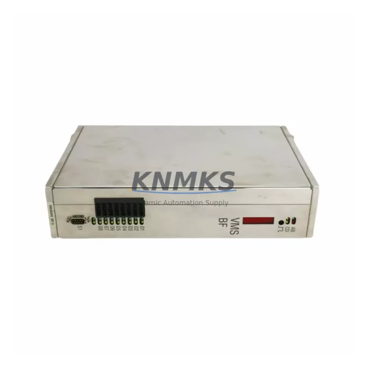
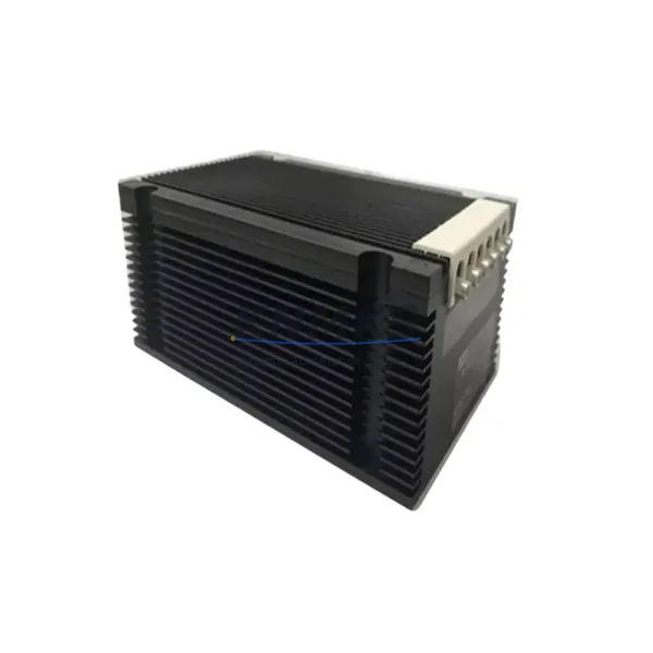
The ORAM LPS 850 (Part No. 295-900913-00, alternate cross-reference 740-805201-02, configuration code R36SSNA-R2-NS-NV-06) is a migration-ready DCS power supply module engineered for direct replacement in aging distributed control system architectures. As legacy ORAM DCS installations approach end-of-support milestones, the LPS 850 provides a verified drop-in solution that eliminates the need for full rack redesign, minimizes field wiring changes, and preserves existing program logic and HMI screen configurations.
This module is specifically suited for retrofit projects where the original power supply has been discontinued, where spare parts availability has become a critical operational risk, or where a phased system upgrade is underway. Engineers and maintenance teams undertaking control cabinet modernization will find the LPS 850 compatible with the original backplane pinout, terminal block layout, and DC bus architecture of the legacy ORAM DCS chassis — reducing commissioning time and the risk of wiring errors during cutover.
Migration Compatibility Table
| Parameter | Specification / Retrofit Guidance |
|---|---|
| Part Number | 295-900913-00 / 740-805201-02 |
| Configuration Code | R36SSNA-R2-NS-NV-06 |
| Module Type | DCS Power Supply Module (LPS 850 Series) |
| Brand | ORAM |
| Backplane Interface | Compatible with original ORAM DCS rack backplane; verify slot position and bus connector alignment before installation |
| Terminal Wiring | Confirm AC input terminal block torque spec and wire gauge match site wiring; no rewiring required for standard configurations |
| Communication Compatibility | Passive power module — no protocol configuration required; verify downstream I/O module addressing is unaffected post-swap |
| Installation Space | Standard ORAM DCS rack slot; confirm physical clearance for adjacent modules (e.g., communication modules, I/O cards) |
| Firmware | No firmware required for power supply module; confirm controller firmware version supports current rack configuration |
| Commissioning Focus | AC input voltage range, DC output load balance, redundancy relay status, and alarm output wiring verification |
| Replacement Recommendation | Direct drop-in for 295-900913-00 and 740-805201-02; functional equivalence confirmed for standard DCS power configurations |
| Support terms | support terms confirmed by quotation — covers manufacturing defects and functional failure under normal operating conditions |
Retrofit Planning for Existing Automation Systems
A successful LPS 850 retrofit begins well before the module arrives on site. During the pre-outage planning phase, engineers should pull the existing rack layout drawing and confirm the power budget across all installed modules. In a typical ORAM DCS cabinet, the power supply feeds a mix of controller cards, analog I/O modules, digital I/O cards, and communication interface modules — each with its own current draw. The LPS 850’s output capacity must be validated against the total rack load, including any recently added expansion modules or signal isolators that may have increased demand since the original system was commissioned.
Terminal block wiring should be documented with photographs before disconnection. The AC input connections, DC output bus bars, and redundancy relay wiring are the three areas most likely to cause commissioning delays if not carefully recorded. Where the legacy installation includes a redundant power supply module in a hot-standby configuration, the changeover relay logic and alarm output wiring must be verified to ensure the new LPS 850 integrates correctly with the existing redundancy scheme.
For sites running older ORAM DCS controller modules alongside the power supply, it is advisable to confirm that the controller’s internal diagnostics do not flag a power supply mismatch after the swap. Some legacy controller firmware versions perform a hardware inventory check at startup; if the replacement module’s hardware revision differs from the original, a firmware update or configuration acknowledgment may be required before the system returns to normal scan operation.
Where the retrofit is part of a broader migration — for example, transitioning from a legacy serial communication architecture to a modern Ethernet-based DCS network — the power supply replacement is typically completed first to stabilize the rack before communication modules or remote I/O interface cards are upgraded. This sequencing ensures that any communication-related commissioning issues are not confused with power-related instability. Similarly, if HMI workstations are being updated in parallel, the power supply cutover should be scheduled independently to isolate variables during the commissioning window.
Signal integrity should be verified after installation using loop checks on critical analog inputs and outputs. Where signal isolators or barrier modules are installed between field instruments and the I/O cards, confirm that the DC supply rail voltage is within tolerance before re-energizing the field loop circuits. A stable, verified power supply is the foundation for all subsequent commissioning steps in a DCS retrofit project.
Downtime Control During System Migration
Minimizing unplanned downtime is the primary operational concern during any DCS power supply replacement. The LPS 850’s drop-in compatibility with the original ORAM rack eliminates the need for backplane modifications, which is the single largest source of extended outage time in legacy power supply retrofits. With the physical swap completed, the system can typically be returned to automatic control within a single planned maintenance window.
To protect existing program logic, the DCS controller should be placed in manual mode and all critical process variables held at their last known good values before power is removed from the rack. Where the control system supports it, a controller memory backup should be performed immediately before the outage begins. This ensures that in the unlikely event of a controller reset during the power supply swap, the application program, I/O configuration, and module addressing can be restored without requiring a full re-download from the engineering workstation.
Field control continuity can be maintained during the cutover window by coordinating with the operations team to place affected control loops in manual at the DCS console. For critical loops — such as those governing pressure, temperature, or flow in safety-instrumented processes — a pre-agreed hold strategy should be documented and reviewed with the shift supervisor before work begins. Once the LPS 850 is installed and DC output voltage is confirmed within specification, loops can be returned to automatic control in a staged sequence, starting with the least critical and progressing to the most critical, to allow the operations team to monitor process response at each step.
Post-installation, a 30-minute observation period is recommended before closing out the work order. During this window, monitor the power supply’s status LEDs, the controller’s diagnostic display, and the DCS alarm summary for any anomalies. Confirm that all I/O modules are communicating normally and that no spurious alarms have been generated by the power transition. Document the as-found and as-left conditions, including DC output voltage measurements, for the site maintenance record.
Retrofit Support FAQ
Q1: Is the ORAM LPS 850 (295-900913-00) a direct replacement for the 740-805201-02?
Yes. The 295-900913-00 and 740-805201-02 are cross-referenced part numbers for the same LPS 850 power supply module. Both references are functionally equivalent and physically interchangeable in the standard ORAM DCS rack. Confirm the configuration code (R36SSNA-R2-NS-NV-06) matches your system’s original specification before ordering.
Q2: What commissioning checks are required after installing the LPS 850?
After installation, verify AC input voltage at the terminal block, measure DC output voltage under load, confirm redundancy relay operation (if applicable), and check that all downstream I/O modules and controller cards have powered up correctly. Review the DCS alarm summary and controller diagnostic log for any fault codes before returning the system to automatic operation.
Q3: Can the LPS 850 be used in a redundant power supply configuration?
Yes, provided the rack and controller configuration support redundant power. Verify that the redundancy relay wiring and changeover logic are compatible with the LPS 850’s alarm output specifications. Where a second power supply slot is available in the rack, a matched pair of LPS 850 modules can be installed to restore hot-standby redundancy.
Q4: What does the support terms confirmed by quotation cover, and what is the stock availability?
The support terms confirmed by quotation cover manufacturing defects and functional failure under normal operating conditions from the date of shipment. We maintain dedicated stock of the LPS 850 (295-900913-00 / 740-805201-02) to support urgent retrofit and breakdown replacement requirements. All units are function-tested prior to shipment. Contact our team for current lead times and regional inventory availability.
© 2026 KNMKS. All rights reserved.
Original Source: https://knmks.com
Contact: admin@knmks.com | +86 18359268345
Product Identification
- Brand / Ecosystem
-
Other Brands
Assorted Brands - Model / Series
-
LPS 850 295-900913-00 740-805201-02 R36SSNA-R2-NS-NV-06
Assorted Series - Product Family
- Power Supplies
- Availability Status
- Available on request after model and quantity confirmation
- Inquiry Type
- B2B RFQ, replacement inquiry and project spare-part request
- Pre-Quote Check
- Exact SKU, brand, series, quantity, nameplate photos and destination country are checked before quotation
System Path
Where this product fits in the KNMKS automation structure.
Specification & Inquiry Focus
- Power range
- DIN rail and switching power supplies
- Common needs
- Voltage, current and mounting style
- Project support
- Control cabinet and panel-builder inquiries
Buyer Confirmation
Information KNMKS checks before replying.
- Exact model
- LPS 850 295-900913-00 740-805201-02 R36SSNA-R2-NS-NV-06
- Brand / ecosystem
- Other Brands
- Product family
- Power Supplies
- Application note
- Replacement, maintenance, project build or spare-part list
- Useful photos
- Nameplate, installed unit, cabinet layout or connector side
- Delivery details
- Quantity, destination country and target schedule
Document Support
Files and notes can be confirmed during quotation.
- Product photos or nameplate confirmation when available
- Packing and delivery notes before quotation confirmation
- Support scope and delivery terms confirmed per inquiry
- Export document coordination for qualified B2B requests
Inquiry Support
- 24VDC and cabinet power selection support
- Stable power support for PLC and HMI systems
- Batch inquiry support for panel builders
What to Send Us
- Brand and exact model number: Other Brands LPS 850 295-900913-00 740-805201-02 R36SSNA-R2-NS-NV-06
- Quantity and required delivery time
- Application, replacement requirement or nameplate photo
- Destination country and shipping preference
RFQ Preparation
This is a product inquiry page built for RFQ communication.
Fast Model Check
Send this model to KNMKS for confirmation.
Include quantity, destination country and photos if this is a maintenance replacement. The inquiry will be saved with a reference number after submission.
Brand & Compatibility Note
KNMKS displays automation product information for well-known industrial brand ecosystems and compatible replacement references. Brand names are used for product identification and compatibility reference only; final availability and commercial terms are confirmed per quotation.
 Manufacturing
 Machine Tools
 Packaging
 Energy & Power
 PLCs & Controllers
 HMI & Displays
 Servo Systems
 Variable Frequency Drives