
Overview
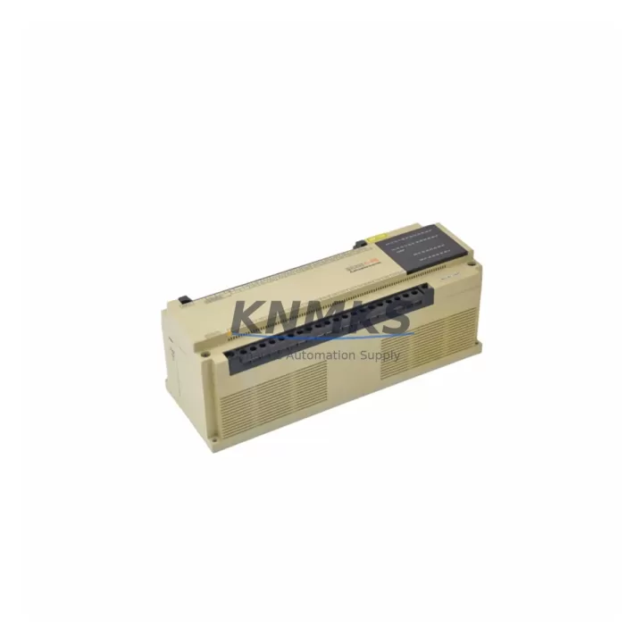
Mitsubishi F2-40ER Migration-Ready Relay PLC for Legacy Control Systems
The Mitsubishi F2-40ER is a 40-point relay output PLC module designed for the MELSEC F2 series — one of Mitsubishi Electric’s most widely deployed compact programmable controller platforms in discrete manufacturing, material handling, and process control applications. As the MELSEC F2 series has reached end-of-life and end-of-support status, engineering teams managing aging control cabinets face increasing pressure to source verified replacement units that preserve existing ladder logic, terminal wiring, and communication architecture without triggering a full system redesign.
The F2-40ER provides a direct migration path for facilities still operating MELSEC F2 base units. With 24 DC input points and 16 relay output points, the module maintains the same I/O count and terminal assignment as the original configuration, allowing retrofit teams to swap the unit without rewiring field devices or modifying PLC program addresses. The relay output design supports resistive, inductive, and lamp loads, making it suitable for motor starter control, solenoid valve switching, and indicator panel interfaces commonly found in legacy control cabinets.
For sites planning a phased migration from MELSEC F2 to a current-generation platform such as the MELSEC iQ-F series (FX5U or FX5UC), the F2-40ER serves as a stabilization module during Phase 1 — maintaining production continuity while engineering teams complete I/O mapping, HMI screen redevelopment, and communication protocol transition planning. During this window, teams should verify backplane slot compatibility, confirm power supply capacity (typically 24 VDC at the F2 base unit), and document all existing GX Developer or FXGP/WIN program files before any hardware swap is executed.
Communication link integrity is a critical checkpoint in any MELSEC F2 retrofit. If the existing system uses CC-Link, RS-422, or RS-232C serial links to upstream SCADA or HMI panels (such as Mitsubishi GOT900 or GOT1000 series terminals), the F2-40ER replacement must be validated against the existing station address settings and baud rate configuration. In parallel, teams should audit any F2-20GM positioning modules or F2-32RM remote I/O units connected to the same rack, as these components share the same backplane bus and may require firmware version alignment after the main CPU or I/O module is replaced.
Installation space confirmation is essential before ordering. The F2-40ER occupies a standard MELSEC F2 base unit slot and ships with the original DIN rail mounting profile. Control cabinet depth, cable routing clearance, and terminal block access should be verified against the existing panel layout drawing. Where cabinets have been modified over time, physical measurement of the available slot width and depth is recommended prior to scheduling the maintenance window.
All F2-40ER units supplied by KNMKS are pre-shipment tested against Mitsubishi Electric factory specifications, covering input response time, relay contact resistance, output load switching, and power consumption under rated conditions. Each unit ships with a support terms confirmed by quotation and is sourced from verified multi-region stock to support both emergency replacement orders and scheduled outage planning. Lead time from confirmed order to dispatch is typically same-day to 3 business days depending on destination region.
Migration Compatibility Table
| Parameter | F2-40ER (Replacement) | Notes / Retrofit Guidance |
|---|---|---|
| Series | MELSEC F2 | Direct replacement for F2 series base unit I/O modules |
| I/O Configuration | 24 DC Inputs / 16 Relay Outputs (40-point total) | Verify terminal assignment matches existing field wiring |
| Output Type | Relay (NO contacts) | Compatible with resistive, inductive, and lamp loads |
| Power Supply Requirement | 24 VDC (supplied via F2 base unit backplane) | Confirm base unit PSU capacity before installation |
| Backplane Interface | MELSEC F2 standard backplane connector | Not compatible with MELSEC FX or Q series backplanes |
| Communication Compatibility | RS-422 / RS-232C via F2 CPU port | Validate baud rate and station address before swap |
| Programming Tool | GX Developer / FXGP/WIN | Back up existing program before hardware replacement |
| Installation Format | DIN rail / panel mount (F2 standard) | Confirm cabinet depth and slot clearance |
| Firmware | Factory-aligned to F2 series specification | No firmware update required for direct replacement |
| Pre-Shipment Testing | Yes — I/O function, relay contact, power consumption | Test report available on request |
| Support terms | 12 Months | Covers manufacturing defects under normal operating conditions |
| Stock Availability | Multi-region stock — same-day to 3-day dispatch | Contact admin@knmks.com for volume and lead time confirmation |
Retrofit Planning for Existing Automation Systems
A successful F2-40ER retrofit begins with a complete audit of the existing MELSEC F2 control cabinet. Engineering teams should document every module installed in the base unit — including the F2-60M or F2-40M CPU module, any F2-32RM remote I/O expansion units, and the F2-20GM positioning module if axis control is part of the application. Understanding the full module inventory prevents unexpected compatibility gaps when the replacement unit is installed and powered up for the first time.
Power budget verification is a non-negotiable step. The F2 series base unit power supply — typically an F2-PA2 or equivalent — must have sufficient headroom to support the F2-40ER’s rated current draw alongside all other installed modules. If the existing PSU is operating near its rated capacity, a power supply upgrade or load redistribution across multiple base units should be planned before the maintenance window opens.
Terminal wiring documentation is equally critical. Field wiring connected to the original I/O module’s terminal block must be photographed and mapped against the F2-40ER terminal assignment diagram before any disconnection occurs. Where terminal labels have faded or been modified over the system’s operational life, continuity testing with a calibrated multimeter should be used to verify each field circuit before reconnection.
For systems where the MELSEC F2 communicates with a Mitsubishi GOT1000 or GOT2000 HMI panel via RS-422 serial link, the HMI project file should be reviewed to confirm that device addresses referenced in screen objects match the program addresses in the F2 CPU. Any address remapping required by the replacement module must be reflected in both the PLC program and the HMI project before the system is returned to service. Signal isolators installed in the communication cable run should also be inspected for compatibility with the replacement module’s signal levels.
Where the retrofit scope extends beyond a single module swap — for example, when replacing an entire F2 base unit or transitioning to a MELSEC iQ-F FX5U platform — teams should plan for I/O expansion using FX5-C32EX/D or FX5-C32ET/D extension modules, and evaluate whether existing programming cables (SC-09 or USB-SC09-FX) are compatible with the new CPU’s programming port before the cutover date.
Downtime Control During System Migration
Minimizing unplanned downtime during a MELSEC F2 module replacement requires a structured pre-outage preparation protocol. The existing PLC program must be read out and saved to a secure backup location using GX Developer or FXGP/WIN before any hardware is disturbed. A second backup copy should be stored on a separate device — USB drive or network share — to protect against data loss during the physical swap.
Where production schedules permit, a bench test of the F2-40ER using a portable 24 VDC power supply and a test terminal block is recommended before the unit is installed in the live cabinet. This confirms relay contact operation, input response, and power consumption under controlled conditions, reducing the risk of discovering a configuration issue during the live maintenance window.
During the physical swap, field wiring should be disconnected from the terminal block in a documented sequence and reconnected to the F2-40ER in the same order. After reconnection, a point-by-point I/O force test — using GX Developer’s device monitor function — should be performed with the PLC in STOP mode before the program is restarted. This verifies that each input and output point is correctly wired and responding before production loads are re-engaged.
Communication link restoration should be the final step before returning the system to AUTO mode. Serial link parameters — baud rate, data bits, stop bits, and station address — should be confirmed against the original system documentation and verified using the GX Developer communication test function. Once communication is confirmed, the PLC program should be restarted in RUN mode and monitored for at least one full production cycle before the maintenance team stands down.
For sites with strict uptime requirements, a cold standby F2-40ER unit held in the local spare parts cabinet eliminates the lead time risk entirely. KNMKS supports standing stock agreements for critical spare parts, allowing facilities to maintain on-site inventory of high-risk modules without committing to large upfront purchases.
Retrofit Support FAQ
Q: Is the F2-40ER a direct drop-in replacement for all MELSEC F2 relay output modules?
A: The F2-40ER is a 40-point relay output module and is a direct replacement for units with the same I/O count and terminal configuration in the MELSEC F2 series. For systems using different point counts (e.g., F2-20ER or F2-60ER configurations), confirm the I/O count and terminal assignment before ordering. Contact admin@knmks.com with your existing module label or cabinet drawing for a compatibility confirmation.
Q: What pre-shipment testing is performed on each F2-40ER unit?
A: Every F2-40ER unit supplied by KNMKS undergoes pre-shipment functional testing covering input response time, relay contact resistance, output switching under rated load, and power consumption at 24 VDC. Test results are available on request. All units are shipped with a support terms confirmed by quotation covering manufacturing defects under normal operating conditions.
Q: Can the F2-40ER be used with GX Works2 or GX Works3 programming software?
A: The MELSEC F2 series is programmed using GX Developer or FXGP/WIN. GX Works2 and GX Works3 do not support the F2 series CPU. If your migration plan includes transitioning to a MELSEC iQ-F or MELSEC-Q platform, the program will need to be converted and validated in the new programming environment before cutover. KNMKS can advise on migration tooling and compatible replacement platforms.
Q: What is the typical lead time and stock availability for the F2-40ER?
A: KNMKS maintains multi-region stock of the F2-40ER to support both emergency replacement and scheduled outage planning. Standard dispatch is same-day to 3 business days from confirmed order, depending on destination region. For volume orders or standing stock agreements, contact admin@knmks.com or call +86 18359268345 for a dedicated supply plan.
© 2026 KNMKS. All rights reserved.
Original Source: https://knmks.com
Contact: admin@knmks.com | +86 18359268345
Product Identification
- Brand / Ecosystem
-
Mitsubishi
Assorted Brands - Model / Series
-
F2-40ER
Assorted Series - Product Family
- PLCs & Controllers
- Availability Status
- Available on request after model and quantity confirmation
- Inquiry Type
- B2B RFQ, replacement inquiry and project spare-part request
- Pre-Quote Check
- Exact SKU, brand, series, quantity, nameplate photos and destination country are checked before quotation
System Path
Where this product fits in the KNMKS automation structure.
Specification & Inquiry Focus
- Control platform
- PLC, PAC and modular controllers
- Common needs
- CPU, rack, power and I/O expansion
- Project support
- Replacement, cabinet build and maintenance
Buyer Confirmation
Information KNMKS checks before replying.
- Exact model
- F2-40ER
- Brand / ecosystem
- Mitsubishi
- Product family
- PLCs & Controllers
- Application note
- Replacement, maintenance, project build or spare-part list
- Useful photos
- Nameplate, installed unit, cabinet layout or connector side
- Delivery details
- Quantity, destination country and target schedule
Document Support
Files and notes can be confirmed during quotation.
- Product photos or nameplate confirmation when available
- Packing and delivery notes before quotation confirmation
- Support scope and delivery terms confirmed per inquiry
- Export document coordination for qualified B2B requests
Inquiry Support
- Model cross-checking before quotation
- CPU, power, rack and expansion module matching
- Support for replacement and project inquiry
What to Send Us
- Brand and exact model number: Mitsubishi F2-40ER
- Quantity and required delivery time
- Application, replacement requirement or nameplate photo
- Destination country and shipping preference
RFQ Preparation
This is a product inquiry page built for RFQ communication.
Fast Model Check
Send this model to KNMKS for confirmation.
Include quantity, destination country and photos if this is a maintenance replacement. The inquiry will be saved with a reference number after submission.
Brand & Compatibility Note
KNMKS displays automation product information for well-known industrial brand ecosystems and compatible replacement references. Brand names are used for product identification and compatibility reference only; final availability and commercial terms are confirmed per quotation.
 Manufacturing
 Machine Tools
 Packaging
 Energy & Power
 HMI & Displays
 Servo Systems
 Variable Frequency Drives
 Sensors