
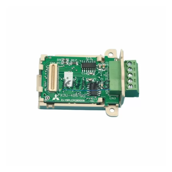
Overview
Mitsubishi D0AOM02 Migration-Ready Output Module for Legacy Control Systems
The Mitsubishi D0AOM02 is a digital output module designed for the MELSEC-F Series programmable logic controller platform. As legacy MELSEC-F installations approach end-of-life or face discontinued spare part availability, the D0AOM02 serves as a verified drop-in replacement that preserves existing wiring configurations, I/O addressing, and program logic without requiring a full system redesign. This module is particularly relevant for facilities managing aging control cabinets where minimizing retrofit scope and downtime is a primary engineering constraint.
For maintenance engineers and automation integrators working on legacy line upgrades, the D0AOM02 addresses one of the most common retrofit bottlenecks: sourcing a functionally equivalent output module that does not require re-engineering the backplane slot assignment, terminal wiring layout, or PLC program output coil mapping. When paired with the Mitsubishi FX1N or FX2N base units still in service across older production lines, the D0AOM02 allows output expansion without disrupting the existing ladder logic structure or forcing a controller migration.
Pre-shipment functional testing is performed on every unit prior to dispatch. Each D0AOM02 is verified against output channel continuity, load switching response, and isolation integrity. A support terms confirmed by quotation is provided from the date of shipment, covering manufacturing defects and verified functional failures under normal operating conditions.
Migration Compatibility Table
| Parameter | D0AOM02 Specification | Retrofit Notes |
|---|---|---|
| Compatible Platform | MELSEC-F Series (FX1N, FX2N, FX3U compatible expansion) | Confirm base unit expansion bus compatibility before installation |
| Output Type | Digital Output (Transistor / Relay — confirm variant) | Match output type to existing load wiring; relay vs. transistor affects response time |
| Terminal Wiring | Screw terminal block, standard pitch | Verify terminal numbering against existing field wiring labels before removal of legacy module |
| Backplane Interface | MELSEC-F expansion connector | No backplane adapter required for direct MELSEC-F slot replacement |
| I/O Address Mapping | Slot-based automatic assignment | Confirm Y-coil address range in existing PLC program matches slot position after replacement |
| Communication Protocol | MELSEC-F internal bus | No protocol reconfiguration required; transparent to CC-Link or RS-485 upper-layer networks |
| Power Supply Requirement | Supplied via base unit / expansion bus | Verify total expansion current draw does not exceed base unit power budget |
| Installation Space | Standard MELSEC-F expansion module form factor | No DIN rail or cabinet modification required for like-for-like replacement |
| Firmware Compatibility | Hardware module — no firmware required | No firmware update needed; compatible with all MELSEC-F base unit firmware versions |
| Support terms | 12 Months from shipment date | Covers manufacturing defects and functional failures under normal operating conditions |
Retrofit Planning for Existing Automation Systems
Successful integration of the D0AOM02 into an existing control system requires a structured pre-replacement audit. Before removing the legacy output module, engineers should document the current Y-coil address assignments in the PLC program using GX Works2 or GX Developer programming software, and confirm that the slot position of the replacement module will produce an identical address map. Any deviation in slot order — particularly when other expansion modules such as analog input cards or communication modules are present in the same rack — can shift the Y-coil base address and cause unexpected output behavior on first power-up.
Terminal wiring documentation is equally critical. Field wiring connected to the legacy module’s output terminals should be photographed and labeled before disconnection. The D0AOM02 uses a standard screw terminal layout consistent with the MELSEC-F expansion family, but terminal numbering should be cross-referenced against the original wiring diagram to avoid transposition errors during reconnection.
For systems where the Mitsubishi FX2N-32MR or FX2N-48MR base unit is the primary controller, the D0AOM02 expansion adds discrete output capacity without requiring changes to the main program scan cycle or interrupt routines. In control cabinets where a Mitsubishi FX2N-4AD analog input module or FX2N-2DA analog output module is also installed, the expansion bus current budget must be recalculated to confirm the power supply margin remains within specification after adding the D0AOM02.
Where the existing system includes a Mitsubishi GOT1000 or GOT2000 HMI panel connected via RS-422 or USB, no HMI screen modifications are required for a like-for-like output module replacement. The HMI tag database references Y-coil addresses in the PLC program, not the physical module slot, so output address continuity is the only variable that must be preserved. If the retrofit scope includes upgrading the communication link from RS-485 to Ethernet using a Mitsubishi FX3U-ENET adapter, this should be planned as a separate phase to isolate variables during commissioning.
For facilities managing multiple legacy lines, maintaining a documented inventory of D0AOM02 units as critical spare parts — with a recommended buffer stock of 2–3 units per production line — significantly reduces unplanned downtime risk. Long-term supply agreements covering 12–36 months of forward inventory are available for high-volume or multi-site requirements.
Downtime Control During System Migration
The primary risk during any output module replacement in a live production environment is uncontrolled output state change during the module swap interval. For the D0AOM02 replacement procedure, the recommended approach is to place the PLC in STOP mode, confirm all controlled outputs are in a safe de-energized state, and isolate field power to the output terminals before removing the legacy module. This sequence protects both field devices and personnel during the physical swap.
Program logic does not need to be modified for a direct D0AOM02 replacement, provided the slot position and Y-coil address mapping are preserved. The existing ladder program, including any output coil interlock conditions, timer-driven sequences, or communication-triggered output routines, remains valid after the module swap. This is a significant advantage over platform migration scenarios where program conversion between instruction sets is required.
After physical installation, the recommended commissioning sequence is: power-up in STOP mode, verify module recognition in the PLC diagnostic display or via GX Works2 online monitoring, then switch to RUN mode and perform a channel-by-channel output verification against the field wiring schedule. For systems with safety-critical outputs — such as motor starters, valve actuators, or conveyor drives — a controlled test cycle should be completed before returning the line to production.
Total replacement time for a trained technician performing a like-for-like D0AOM02 swap, including wiring verification and output commissioning, is typically 30–90 minutes depending on cabinet accessibility and the number of output channels requiring individual verification. Pre-shipment testing of the replacement unit eliminates the risk of receiving a non-functional module, which is the most common cause of extended unplanned downtime during spare part replacements.
Retrofit Support FAQ
Q: Is the D0AOM02 a direct replacement for the original MELSEC-F output module without program changes?
A: Yes, provided the replacement module is installed in the same backplane slot position as the original. The Y-coil address assignment is slot-dependent in the MELSEC-F architecture. If the slot position changes, the Y-coil base address will shift and the PLC program will require address remapping before the system can be returned to service.
Q: What pre-shipment testing is performed on each D0AOM02 unit?
A: Each unit undergoes output channel continuity verification, load switching functional test, and isolation integrity check before dispatch. Test records are available upon request. All units are shipped with a support terms confirmed by quotation covering manufacturing defects and functional failures under normal operating conditions.
Q: Can the D0AOM02 be used in a mixed expansion rack alongside analog and communication modules?
A: Yes. The D0AOM02 is compatible with mixed MELSEC-F expansion configurations. However, the total expansion bus current draw must be calculated to confirm the base unit power supply budget is not exceeded. This calculation should include all expansion modules present in the rack, including analog input/output cards and any communication adapters.
Q: What is the lead time and stock availability for the D0AOM02?
A: Stock is maintained for immediate dispatch. For planned maintenance programs or multi-site deployments, long-term supply agreements covering 12–36 months of forward inventory are available. Contact the sales team to confirm current stock levels and arrange priority allocation for critical spare part requirements.
© 2026 KNMKS. All rights reserved.
Original Source: https://knmks.com
Contact: admin@knmks.com | +86 18359268345
Product Identification
- Brand / Ecosystem
-
Mitsubishi Electric
Assorted Brands - Model / Series
-
D0AOM02
Assorted Series - Product Family
- PLCs & Controllers
- Availability Status
- Available on request after model and quantity confirmation
- Inquiry Type
- B2B RFQ, replacement inquiry and project spare-part request
- Pre-Quote Check
- Exact SKU, brand, series, quantity, nameplate photos and destination country are checked before quotation
System Path
Where this product fits in the KNMKS automation structure.
Specification & Inquiry Focus
- Control platform
- PLC, PAC and modular controllers
- Common needs
- CPU, rack, power and I/O expansion
- Project support
- Replacement, cabinet build and maintenance
Buyer Confirmation
Information KNMKS checks before replying.
- Exact model
- D0AOM02
- Brand / ecosystem
- Mitsubishi Electric
- Product family
- PLCs & Controllers
- Application note
- Replacement, maintenance, project build or spare-part list
- Useful photos
- Nameplate, installed unit, cabinet layout or connector side
- Delivery details
- Quantity, destination country and target schedule
Document Support
Files and notes can be confirmed during quotation.
- Product photos or nameplate confirmation when available
- Packing and delivery notes before quotation confirmation
- Support scope and delivery terms confirmed per inquiry
- Export document coordination for qualified B2B requests
Inquiry Support
- Model cross-checking before quotation
- CPU, power, rack and expansion module matching
- Support for replacement and project inquiry
What to Send Us
- Brand and exact model number: Mitsubishi Electric D0AOM02
- Quantity and required delivery time
- Application, replacement requirement or nameplate photo
- Destination country and shipping preference
RFQ Preparation
This is a product inquiry page built for RFQ communication.
Fast Model Check
Send this model to KNMKS for confirmation.
Include quantity, destination country and photos if this is a maintenance replacement. The inquiry will be saved with a reference number after submission.
Brand & Compatibility Note
KNMKS displays automation product information for well-known industrial brand ecosystems and compatible replacement references. Brand names are used for product identification and compatibility reference only; final availability and commercial terms are confirmed per quotation.
 Manufacturing
 Machine Tools
 Packaging
 Energy & Power
 HMI & Displays
 Servo Systems
 Variable Frequency Drives
 Sensors