
Overview
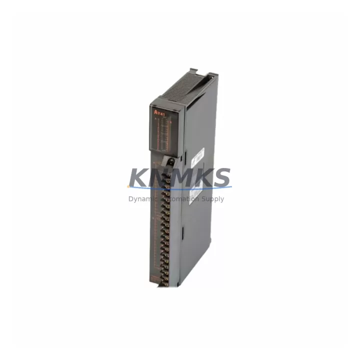
MITSUBISHI AY41 Maintenance-Proven Spare Part for Factory Uptime
The MITSUBISHI AY41 is a 32-point transistor output module designed for the MELSEC-A series programmable logic controller platform. In industrial maintenance environments — from automotive assembly lines to chemical processing plants — the AY41 serves as a critical interface between the PLC CPU and field actuators, solenoid valves, relay coils, and indicator lamps. When an AY41 fails or degrades, the downstream impact is immediate: output signals drop, actuators freeze, and production halts. Holding a verified, pre-tested AY41 spare in your maintenance inventory is one of the most cost-effective decisions a maintenance engineer can make for MELSEC-A-based control systems.
This listing covers an original MITSUBISHI AY41 output module sourced from authorized supply channels, pre-shipment tested for output channel integrity, inrush current tolerance, and backplane communication, and backed by a support terms confirmed by quotation. Multi-region stock is maintained to support both emergency same-week dispatch and scheduled annual outage procurement.
Spare Maintenance Table
| Parameter | Specification |
|---|---|
| SKU / Part Number | AY41 |
| Brand | MITSUBISHI Electric |
| Series | MELSEC-A (A Series) |
| Module Type | Transistor Output Module |
| Output Points | 32 Points |
| Output Type | Transistor (Sink / NPN) |
| Rated Load Voltage | 12–24 VDC |
| Max Load Current per Point | 0.1 A |
| Max Load Current (All Points ON) | 3.2 A |
| Isolation Method | Photocoupler |
| Response Time (OFF→ON) | ≤ 1 ms |
| Response Time (ON→OFF) | ≤ 1 ms |
| Connector Type | 40-pin connector (A-series backplane compatible) |
| Compatible CPUs | A1S, A2S, A2SH, A3, A3H, A3M, A1N, A2N, A3N and compatible A-series CPUs |
| Operating Temperature | 0 °C to 55 °C |
| Storage Temperature | -20 °C to 75 °C |
| Humidity | 5% to 95% RH (non-condensing) |
| Weight | Approx. 1,070 g (with connector) |
| Origin | Japan |
| Support terms | 12 Months from shipment date |
| Pre-Shipment Test | Yes — output channel integrity, backplane communication, load switching |
| Stock Availability | Multi-region stock; emergency dispatch supported |
Maintenance Planning for Continuous Operation
When an AY41 output module is flagged during routine control cabinet inspection or fails during a production shift, the replacement scope rarely ends at the module itself. Experienced maintenance engineers treat an AY41 fault as a trigger for a broader cabinet audit to prevent cascading failures and reduce the risk of repeat downtime.
Start with the A-series backplane or base unit (such as the A1S-52B or A38B). Connector pin wear, backplane slot corrosion, or cracked bus connectors can cause intermittent output faults that mimic a failed AY41. Inspect the slot contacts and reseat the module before condemning it. If the backplane shows physical damage or bus errors, it should be replaced concurrently.
Next, verify the 24 VDC field power supply feeding the AY41 output commons. Voltage sag, ripple, or a failing power supply unit — such as the A1S61PN or equivalent MELSEC-A power module — can cause transistor output channels to behave erratically under load. Measure supply voltage at the module terminal under full load before signing off on the replacement.
Check the external fuse or circuit protection on each output common. Blown fuses on the output commons are a frequent companion fault when an AY41 fails due to an inductive load spike. Replace any blown fuses and consider adding surge suppressors across inductive loads (solenoid valves, relay coils) to extend the service life of the replacement module.
If the AY41 drives relay coils or contactor coils, inspect the intermediate relay bank in the same cabinet. Relay contacts that have welded shut or coils with degraded insulation can back-feed voltage into the transistor outputs, causing premature failure. Relay modules such as the MITSUBISHI A1SY10 or equivalent relay output modules in adjacent slots should be checked for contact resistance and coil current draw.
For systems where the AY41 interfaces with signal isolators or I/O terminal blocks, verify that the isolator output voltage matches the AY41 input requirements and that terminal block screws are torqued to specification. Loose terminals are a leading cause of intermittent output faults in high-vibration environments.
Finally, if the MELSEC-A system includes a communication module such as the A1SJ71UC24-R2 or an Ethernet interface card, confirm that the CPU is not logging output module errors or bus timeout faults that could indicate a deeper backplane or CPU issue rather than an isolated AY41 failure.
Site Replacement Workflow
Step 1 — Isolate and document. Before removing the AY41, record the current output status via the CPU programmer or HMI. Note which output points were active, which were faulted, and the last known load current readings. This baseline is essential for post-replacement verification.
Step 2 — De-energize safely. Switch the PLC to STOP mode via the CPU keyswitch or programming software (GX Developer or GX Works2 for legacy A-series). Isolate the 24 VDC field power supply to the AY41 output commons. Verify zero voltage at the output terminals with a calibrated multimeter before proceeding.
Step 3 — Remove and inspect. Disconnect the 40-pin output connector. Remove the AY41 from the backplane slot. Inspect the connector pins for burn marks, corrosion, or mechanical deformation. Inspect the backplane slot contacts. If either shows damage, address before installing the replacement.
Step 4 — Install the replacement AY41. Seat the new AY41 firmly into the backplane slot until the connector is fully engaged. Reconnect the 40-pin field wiring connector. Verify that the module LED indicators illuminate correctly upon power-up (RUN LED on, ERR LED off).
Step 5 — Functional verification. Switch the CPU to RUN mode. Force-test each output point using the programming software monitor function. Verify that all 32 output channels switch correctly under load. Confirm that the HMI reflects the correct output states and that no error codes are logged in the CPU diagnostic buffer.
Step 6 — Document and close. Record the replacement date, new module serial number, and test results in the maintenance log. Update the spare parts inventory to trigger reorder of a replacement AY41 for the next maintenance cycle.
Spare Parts Support FAQ
Q1: Is this AY41 compatible with all MELSEC-A series base units?
The AY41 is compatible with the full range of MELSEC-A series base units, including the A1S-52B, A38B, A38HB, and A68B, as well as A1N, A2N, A3N, A1S, A2S, A2SH, and A3-series CPU configurations. If your system uses a non-standard or modified backplane, please provide the base unit model number at the time of inquiry for compatibility confirmation before shipment.
Q2: What does the support terms confirmed by quotation cover, and what is the claims process?
The support terms confirmed by quotation cover manufacturing defects, output channel failure under normal operating conditions, and backplane interface faults. It does not cover damage caused by incorrect installation, overvoltage, reverse polarity, or physical impact. To initiate a support terms claim, contact admin@knmks.com with the order number, fault description, and photographic evidence of the defect. Replacement or repair will be arranged within 5 business days of claim approval.
Q3: Can you support long-term or blanket purchase orders for AY41 spares?
Yes. KNMKS supports long-term supply agreements and blanket purchase orders for AY41 and other MELSEC-A series modules. Multi-region stock is maintained specifically to support annual outage schedules, rolling maintenance programs, and emergency call-off orders. Contact admin@knmks.com to discuss volume pricing, lead time commitments, and consignment stock arrangements.
Q4: How is the AY41 tested before shipment?
Every AY41 unit undergoes a pre-shipment test protocol that includes: (1) output channel switching test across all 32 points under rated load, (2) backplane communication integrity check, (3) photocoupler isolation verification, and (4) visual inspection for connector pin condition and PCB integrity. A test report is available upon request for units destined for critical infrastructure or regulated industries.
© 2026 KNMKS. All rights reserved.
Original Source: https://knmks.com
Contact: admin@knmks.com | +86 18359268345
Product Identification
- Brand / Ecosystem
-
Mitsubishi
Assorted Brands - Model / Series
-
AY41
Assorted Series - Product Family
- PLCs & Controllers
- Availability Status
- Available on request after model and quantity confirmation
- Inquiry Type
- B2B RFQ, replacement inquiry and project spare-part request
- Pre-Quote Check
- Exact SKU, brand, series, quantity, nameplate photos and destination country are checked before quotation
System Path
Where this product fits in the KNMKS automation structure.
Specification & Inquiry Focus
- Control platform
- PLC, PAC and modular controllers
- Common needs
- CPU, rack, power and I/O expansion
- Project support
- Replacement, cabinet build and maintenance
Buyer Confirmation
Information KNMKS checks before replying.
- Exact model
- AY41
- Brand / ecosystem
- Mitsubishi
- Product family
- PLCs & Controllers
- Application note
- Replacement, maintenance, project build or spare-part list
- Useful photos
- Nameplate, installed unit, cabinet layout or connector side
- Delivery details
- Quantity, destination country and target schedule
Document Support
Files and notes can be confirmed during quotation.
- Product photos or nameplate confirmation when available
- Packing and delivery notes before quotation confirmation
- Support scope and delivery terms confirmed per inquiry
- Export document coordination for qualified B2B requests
Inquiry Support
- Model cross-checking before quotation
- CPU, power, rack and expansion module matching
- Support for replacement and project inquiry
What to Send Us
- Brand and exact model number: Mitsubishi AY41
- Quantity and required delivery time
- Application, replacement requirement or nameplate photo
- Destination country and shipping preference
RFQ Preparation
This is a product inquiry page built for RFQ communication.
Fast Model Check
Send this model to KNMKS for confirmation.
Include quantity, destination country and photos if this is a maintenance replacement. The inquiry will be saved with a reference number after submission.
Brand & Compatibility Note
KNMKS displays automation product information for well-known industrial brand ecosystems and compatible replacement references. Brand names are used for product identification and compatibility reference only; final availability and commercial terms are confirmed per quotation.
 Manufacturing
 Machine Tools
 Packaging
 Energy & Power
 HMI & Displays
 Servo Systems
 Variable Frequency Drives
 Sensors