
Overview
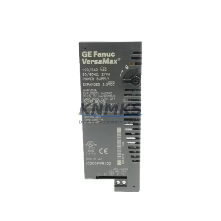
GE IC200PWR102 Migration-Ready Power Supply for Legacy Control Systems
The GE IC200PWR102 is a 24VDC input power supply module designed for the VersaMax Micro platform, one of GE Automation’s (now Emerson) most widely deployed compact PLC families in light manufacturing, building automation, and process control applications. As legacy VersaMax Micro installations approach end-of-life or face discontinued spare part availability, the IC200PWR102 serves as a critical migration-ready replacement that preserves existing wiring infrastructure, backplane compatibility, and control logic continuity.
For engineers managing aging control cabinets, the IC200PWR102 offers a direct drop-in solution that eliminates the need for full panel redesign. Its 24VDC input range aligns with standard industrial power distribution architectures, and its compact form factor fits within existing DIN rail or panel-mount enclosures without requiring additional installation space. When combined with compatible I/O modules such as the IC200MDL640 (discrete input) or IC200MDL741 (discrete output), the IC200PWR102 supports a complete rack-level power restoration without disrupting field wiring or PLC program logic.
Procurement teams sourcing replacement power supplies for VersaMax Micro systems should verify the input voltage specification (24VDC nominal, 20.4–28.8VDC operating range), output current capacity, and backplane connector alignment before installation. The IC200PWR102 is fully compatible with the standard VersaMax Micro base units and does not require firmware updates on the CPU module — a key advantage when minimizing downtime during unplanned failures or scheduled maintenance windows.
Migration Compatibility Table
| Parameter | IC200PWR102 Specification | Retrofit / Migration Notes |
|---|---|---|
| Input Voltage | 24VDC (20.4–28.8VDC) | Compatible with standard 24VDC panel power rails; no rewiring required |
| Backplane Interface | VersaMax Micro backplane connector | Direct replacement for existing IC200PWR101 / IC200PWR102 installations |
| Installation Format | Integrated module (no separate mounting) | Fits existing enclosure footprint; no panel modification needed |
| Communication Compatibility | Passive power module; no protocol dependency | Compatible with Profibus, DeviceNet, Ethernet/IP CPU variants on same rack |
| CPU Compatibility | All VersaMax Micro CPU variants | No firmware update required on CPU after power supply replacement |
| Replacement Recommendation | Direct drop-in for discontinued IC200PWR102 | Verify output current budget against total I/O module load before installation |
| Commissioning Focus | Power-on sequence, backplane seating, LED status check | Confirm OK LED illuminates; verify CPU enters RUN mode without fault |
| Support terms | support terms confirmed by quotation | Covered from date of shipment; includes DOA replacement and technical support |
Retrofit Planning for Existing Automation Systems
Successful retrofit of a VersaMax Micro power supply requires a structured pre-installation assessment. Before removing the existing power module, engineers should document the current power budget across all installed I/O modules. A typical VersaMax Micro rack may include a combination of analog input modules such as the IC200ALG260, thermocouple input modules, and high-density discrete I/O — each drawing current from the backplane. The IC200PWR102 must be confirmed to supply sufficient current headroom for the full module complement.
Terminal wiring on the IC200PWR102 follows the standard VersaMax Micro screw-terminal layout. Field wiring from the 24VDC supply should be verified for correct polarity and wire gauge before reconnection. In installations where the power supply is co-located with a VersaMax Micro PROFIBUS adapter (IC200BEM003) or an Ethernet communications module, the communication link should be tested immediately after power restoration to confirm that the network address and baud rate settings have been retained in the CPU’s non-volatile memory.
For control cabinets undergoing broader modernization — such as migration from a standalone VersaMax Micro to a networked PACSystems RX3i architecture — the IC200PWR102 can serve as an interim power solution while the new control platform is commissioned in parallel. This staged approach allows the existing HMI screens (typically connected via serial RS-232 or RS-485 to the VersaMax CPU) to remain operational during the transition, reducing the risk of production interruption. Programming cables such as the IC200CBL001 or USB-to-serial adapters remain compatible with the existing CPU during this interim period.
Signal isolation requirements should also be reviewed during retrofit planning. In applications where analog signals share a common ground with the 24VDC power rail, installing a signal isolator between field instruments and the analog input modules prevents ground loop interference after the power supply is replaced. This is particularly relevant in petrochemical and energy sector installations where intrinsic safety barriers and galvanic isolators are standard practice.
Downtime Control During System Migration
Minimizing unplanned downtime during a VersaMax Micro power supply replacement requires preparation at three levels: program backup, hardware staging, and field verification. Before any module is removed, the existing PLC program should be uploaded and saved using Proficy Machine Edition or the legacy VersaPro programming environment. This backup preserves all rung logic, data table values, retentive register contents, and communication configuration — ensuring that the replacement power supply installation does not result in program loss if the CPU loses power unexpectedly during the swap.
Hardware staging involves pre-testing the IC200PWR102 on a bench setup before installation in the live panel. Applying 24VDC to the module and confirming the OK status LED illuminates takes less than five minutes and eliminates the risk of installing a defective unit into a production system. All units supplied by KNMKS are pre-tested prior to shipment as part of standard outgoing quality control.
During the physical swap, the control system should be placed in STOP mode and the 24VDC supply isolated at the panel disconnect. The backplane connector should be inspected for bent pins or contamination before the new IC200PWR102 is seated. After installation, power should be restored in sequence: panel supply first, then CPU power-up, followed by confirmation that all I/O modules return to their pre-fault states. Field devices connected to discrete output modules should be verified against the HMI status display before returning the system to AUTO mode.
For installations with redundant control paths or safety relay circuits, the migration plan should include a functional test of all safety interlocks after power restoration. This step is non-negotiable in applications governed by IEC 61511 or NFPA 79 compliance requirements.
Retrofit Support FAQ
Q1: Is the IC200PWR102 a direct replacement for all VersaMax Micro power supply variants?
The IC200PWR102 is specifically designed for 24VDC input applications. If your existing installation uses an AC-input power supply variant, verify the input voltage specification on the module label before ordering. For 24VDC systems, the IC200PWR102 is a direct drop-in replacement with no wiring or backplane modifications required.
Q2: Will replacing the power supply erase the PLC program stored in the CPU?
The VersaMax Micro CPU stores its program in non-volatile flash memory, which is independent of the power supply module. Under normal conditions, replacing the IC200PWR102 does not affect the stored program. However, KNMKS recommends uploading and saving a program backup before any hardware replacement as a standard precaution.
Q3: What commissioning steps are required after installing the IC200PWR102?
After seating the module and restoring 24VDC power, confirm the OK LED on the power supply illuminates steadily. Verify the CPU enters RUN mode and that all I/O module status LEDs indicate normal operation. Test communication links (Ethernet, PROFIBUS, or serial) to confirm network connectivity is restored. Perform a functional I/O check against the HMI before returning the system to automatic control.
Q4: What support terms and supply terms does KNMKS offer for the IC200PWR102?
All IC200PWR102 units supplied by KNMKS carry a support terms confirmed by quotation from the date of shipment, covering manufacturing defects and DOA (dead-on-arrival) failures. Units are pre-tested prior to dispatch. Inventory is maintained in Xiamen for prompt shipment. For volume procurement, blanket order and consignment stock arrangements are available — contact the sales team for details.
© 2026 KNMKS. All rights reserved.
Original Source: https://knmks.com
Contact: admin@knmks.com | +86 18359268345
Product Identification
- Brand / Ecosystem
-
GE
Assorted Brands - Model / Series
-
IC200PWR102
Assorted Series - Product Family
- Power Supplies
- Availability Status
- Available on request after model and quantity confirmation
- Inquiry Type
- B2B RFQ, replacement inquiry and project spare-part request
- Pre-Quote Check
- Exact SKU, brand, series, quantity, nameplate photos and destination country are checked before quotation
System Path
Where this product fits in the KNMKS automation structure.
Specification & Inquiry Focus
- Power range
- DIN rail and switching power supplies
- Common needs
- Voltage, current and mounting style
- Project support
- Control cabinet and panel-builder inquiries
Buyer Confirmation
Information KNMKS checks before replying.
- Exact model
- IC200PWR102
- Brand / ecosystem
- GE
- Product family
- Power Supplies
- Application note
- Replacement, maintenance, project build or spare-part list
- Useful photos
- Nameplate, installed unit, cabinet layout or connector side
- Delivery details
- Quantity, destination country and target schedule
Document Support
Files and notes can be confirmed during quotation.
- Product photos or nameplate confirmation when available
- Packing and delivery notes before quotation confirmation
- Support scope and delivery terms confirmed per inquiry
- Export document coordination for qualified B2B requests
Inquiry Support
- 24VDC and cabinet power selection support
- Stable power support for PLC and HMI systems
- Batch inquiry support for panel builders
What to Send Us
- Brand and exact model number: GE IC200PWR102
- Quantity and required delivery time
- Application, replacement requirement or nameplate photo
- Destination country and shipping preference
RFQ Preparation
This is a product inquiry page built for RFQ communication.
Fast Model Check
Send this model to KNMKS for confirmation.
Include quantity, destination country and photos if this is a maintenance replacement. The inquiry will be saved with a reference number after submission.
Brand & Compatibility Note
KNMKS displays automation product information for well-known industrial brand ecosystems and compatible replacement references. Brand names are used for product identification and compatibility reference only; final availability and commercial terms are confirmed per quotation.
 Manufacturing
 Machine Tools
 Packaging
 Energy & Power
 PLCs & Controllers
 HMI & Displays
 Servo Systems
 Variable Frequency Drives