
Overview
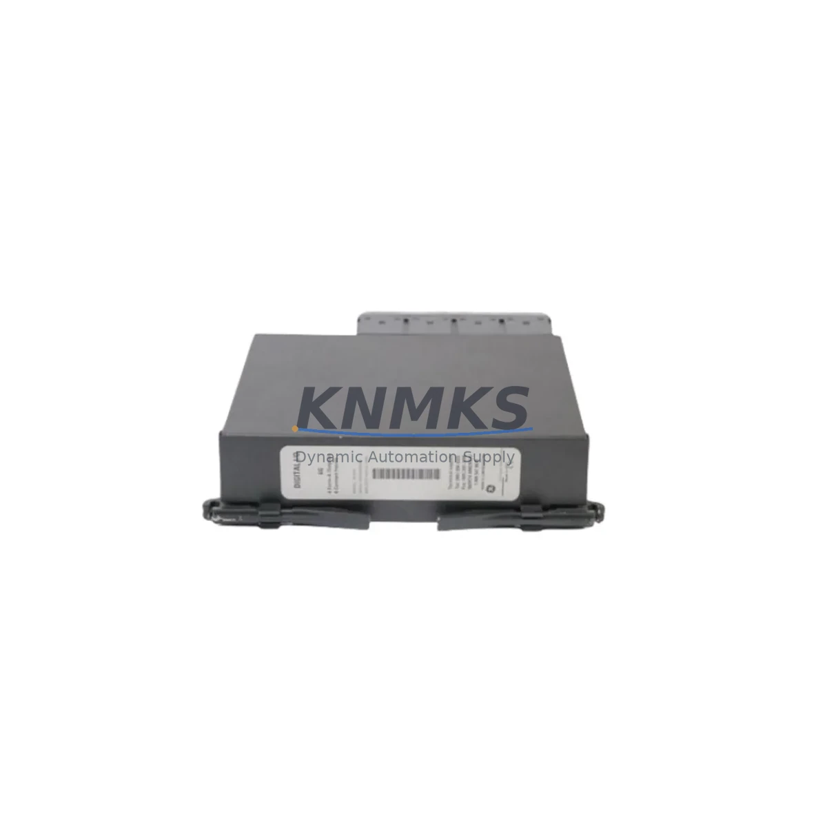
Bently Nevada 991-05-50-01-00 Migration-Ready Axial Position Transmitter for Legacy Control Systems
The Bently Nevada 991-05-50-01-00 is a precision axial position transmitter designed for integration within the Bently Nevada 3500 Series machinery protection platform. As original equipment reaches end-of-life and OEM support windows close, facilities managing rotating machinery — including steam turbines, gas compressors, centrifugal pumps, and large induction motors — increasingly require verified replacement units that can be installed without reprogramming the host rack or reconfiguring the monitoring software. The 991-05-50-01-00 fulfills this requirement directly: it is a migration-ready, drop-in compatible replacement for legacy axial position monitoring applications where the original module has failed, degraded, or been discontinued.
Before committing to a replacement, engineers must confirm several critical parameters. Power supply capacity within the 3500 rack must be sufficient to support the transmitter alongside co-installed modules such as the 3500/42M Proximitor/Seismic Monitor or the 3500/22M Transient Data Interface. Terminal wiring must be verified against the original I/O drawing — particularly the Keyphasor input connections and the 4–20 mA output loop wiring — to avoid signal inversion or ground loop issues during commissioning. Backplane slot addressing must match the original configuration stored in the 3500 Rack Configuration Utility, and any changes to module address must be reflected in System 1 or equivalent condition monitoring software before the unit is brought online. Firmware version compatibility between the 991-05-50-01-00 and the installed rack firmware should be confirmed prior to installation, especially in racks running mixed-generation modules.
For facilities operating legacy Bently Nevada 7200 Series or 3300 Series systems, the migration path to the 3500 platform requires additional planning. The 3500/20 Rack Interface Module and 3500/15 Power Supply Module are typically the first components replaced during a rack-level upgrade, followed by position and vibration monitoring modules. The 991-05-50-01-00 is positioned within this upgrade sequence as the axial position sensing element, working in conjunction with proximity probes and extension cables already installed in the machine train. Where the original probe system uses 7200 Series extension cables, compatibility with the 3500 rack’s input impedance specifications must be verified before reuse.
In control cabinet retrofit projects, installation space is a frequent constraint. The 991-05-50-01-00 occupies a standard 3500 Series module slot and does not require additional DIN rail mounting or external signal conditioning. However, where the cabinet also houses a 3500/92 Communication Gateway Module for Modbus or PROFIBUS integration, the communication link configuration must be updated to reflect the new module’s channel assignments. HMI screens connected via the gateway — whether running on a legacy Wonderware InTouch node or a modern FactoryTalk View SE station — must have their tag databases updated to match the new channel mapping before the system is returned to service.
Downtime during axial position transmitter replacement is a significant operational concern in continuous-process industries. A structured pre-installation checklist — covering power isolation, probe gap verification, signal loop testing, and rack configuration backup — reduces the risk of extended outages. Our pre-shipment testing protocol validates each 991-05-50-01-00 unit against Bently Nevada factory specifications before dispatch, including output linearity, zero and span calibration, and power consumption verification. Units are shipped with a support terms confirmed by quotation covering manufacturing defects and functional performance.
Migration Compatibility Table
| Parameter | Details |
|---|---|
| Compatible Rack | Bently Nevada 3500 Series |
| Module Type | Axial Position Transmitter |
| Output Signal | 4–20 mA analog, configurable |
| Input Interface | Proximitor probe / extension cable |
| Backplane Compatibility | 3500 Series standard backplane slot |
| Communication Protocol | Compatible with 3500/92 Modbus / PROFIBUS gateway |
| Legacy Replacement Path | Bently Nevada 7200 / 3300 Series axial position modules |
| Power Requirement | Supplied via 3500 rack backplane (verify 3500/15 PSU capacity) |
| Installation Space | Standard 3500 module slot — no external mounting required |
| Firmware Compatibility | Verify rack firmware version before installation |
| Commissioning Tool | 3500 Rack Configuration Utility / System 1 software |
| Pre-Shipment Testing | Output linearity, zero/span calibration, power consumption |
| Support terms | 12 months from date of shipment |
Retrofit Planning for Existing Automation Systems
A complete axial position monitoring retrofit within a 3500 Series rack typically involves coordinating several interdependent components. The 3500/15 Power Supply Module must be assessed first — its output capacity determines how many monitoring modules can be active simultaneously. Where the existing PSU is at or near capacity, a second power supply may be required before the 991-05-50-01-00 is added to the rack. The 3500/20 Rack Interface Module governs communication between the rack and the host monitoring system; its configuration file must be updated whenever a new module is installed or an existing module’s slot address changes.
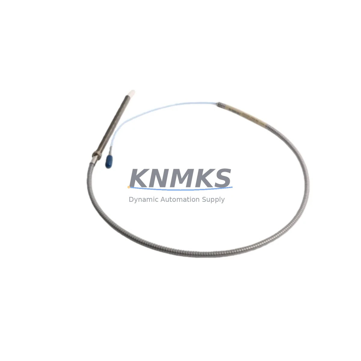
Probe system integrity is equally important. The 991-05-50-01-00 operates with standard Bently Nevada proximity probes and extension cables. Where the installed probe is a 3300 XL 8mm or 3300 XL 11mm type, gap voltage and sensitivity specifications must be re-verified against the transmitter’s input range. If the existing extension cable has been in service for more than five years, insulation resistance testing is recommended before reuse. In applications where the machine train also requires radial vibration monitoring, the 3500/42M Proximitor/Seismic Monitor is typically installed in an adjacent slot, sharing the same rack power and communication infrastructure.
For facilities that have already migrated their SCADA or DCS layer to a modern platform, the 3500/92 Communication Gateway Module provides the Modbus TCP or PROFIBUS DP interface required to pass axial position data upstream. Tag mapping between the gateway and the host system — whether a Siemens S7-300 PLC, a Rockwell ControlLogix controller, or a Honeywell Experion PKS node — must be updated to reflect the new module’s data register assignments. Where a programming cable such as the 3500 Series RS-232 configuration cable is used for local rack access, the cable pinout and COM port settings must be confirmed before attempting configuration changes.
Downtime Control During System Migration
Minimizing unplanned downtime during an axial position transmitter replacement requires a disciplined pre-outage preparation sequence. Before the maintenance window opens, the existing rack configuration should be exported and archived using the 3500 Rack Configuration Utility. This backup preserves all module addresses, alarm setpoints, and I/O assignments, allowing rapid restoration if the replacement unit requires reconfiguration. The original probe gap measurement should be recorded and compared against the manufacturer’s recommended gap voltage for the installed probe type — any deviation must be corrected before the new transmitter is commissioned.
During the replacement, the machine train should be confirmed at rest and the rack power isolated at the 3500/15 Power Supply Module before the module is removed. After the 991-05-50-01-00 is seated in the backplane slot, power is restored and the rack configuration is downloaded to the new module. Output loop continuity is verified at the field terminal block before the monitoring system is returned to automatic mode. Where the facility operates a redundant monitoring architecture, the standby channel should be confirmed healthy before the primary channel is taken offline, ensuring continuous protection of the machine train throughout the replacement procedure.
Our logistics team maintains in-stock inventory of the 991-05-50-01-00 to support emergency replacement requirements. Standard lead time for verified, pre-tested units is 1–3 business days. Each unit ships with a test report and is covered by a support terms confirmed by quotation, reducing the risk associated with unplanned outages and supporting the facility’s spare parts lifecycle management program.
Retrofit Support FAQ
Q: Is the 991-05-50-01-00 a direct replacement for legacy Bently Nevada axial position modules in 3300 or 7200 Series racks?
A: The 991-05-50-01-00 is designed for the 3500 Series rack platform. Migration from 3300 or 7200 Series racks requires a rack-level upgrade to the 3500 platform, including replacement of the power supply and rack interface modules. The 991-05-50-01-00 is then installed as the axial position monitoring element within the upgraded rack.
Q: What commissioning steps are required after installation?
A: After seating the module and restoring rack power, download the archived rack configuration using the 3500 Rack Configuration Utility. Verify probe gap voltage, confirm output loop continuity at the field terminal block, and validate alarm setpoints in System 1 or the connected condition monitoring platform. Update HMI tag databases if channel assignments have changed.
Q: How is wiring compatibility confirmed before installation?
A: Compare the existing I/O drawing against the 991-05-50-01-00 terminal assignment diagram. Pay particular attention to Keyphasor input wiring, 4–20 mA output loop polarity, and shield grounding practice. Where the original wiring used a different terminal block pitch or connector type, an adapter terminal block may be required.
Q: What does the support terms confirmed by quotation cover, and is pre-shipment testing included?
A: Each 991-05-50-01-00 unit undergoes pre-shipment functional testing covering output linearity, zero and span calibration, and power consumption verification. The support terms confirmed by quotation cover manufacturing defects and functional performance failures under normal operating conditions. A test report is included with each shipment. Contact admin@knmks.com or +86 18359268345 for support requests or technical support.
© 2026 KNMKS. All rights reserved.
Original Source: https://knmks.com
Contact: admin@knmks.com | +86 18359268345
Product Identification
- Brand / Ecosystem
-
Bently Nevada
Bently Nevada - Model / Series
-
991-05-50-01-00
3500 Series - Product Family
- Sensors
- Availability Status
- Available on request after model and quantity confirmation
- Inquiry Type
- B2B RFQ, replacement inquiry and project spare-part request
- Pre-Quote Check
- Exact SKU, brand, series, quantity, nameplate photos and destination country are checked before quotation
System Path
Where this product fits in the KNMKS automation structure.
Specification & Inquiry Focus
- Sensor range
- Photoelectric, proximity and process sensors
- Common needs
- Output type, distance and connector
- Project support
- Machine detection and replacement inquiry
Buyer Confirmation
Information KNMKS checks before replying.
- Exact model
- 991-05-50-01-00
- Brand / ecosystem
- Bently Nevada
- Product family
- Sensors
- Application note
- Replacement, maintenance, project build or spare-part list
- Useful photos
- Nameplate, installed unit, cabinet layout or connector side
- Delivery details
- Quantity, destination country and target schedule
Document Support
Files and notes can be confirmed during quotation.
- Product photos or nameplate confirmation when available
- Packing and delivery notes before quotation confirmation
- Support scope and delivery terms confirmed per inquiry
- Export document coordination for qualified B2B requests
Inquiry Support
- NPN/PNP, analog and digital output checking
- Connector and cable compatibility review
- Fast inquiry support for maintenance teams
What to Send Us
- Brand and exact model number: Bently Nevada 991-05-50-01-00
- Quantity and required delivery time
- Application, replacement requirement or nameplate photo
- Destination country and shipping preference
RFQ Preparation
This is a product inquiry page built for RFQ communication.
Fast Model Check
Send this model to KNMKS for confirmation.
Include quantity, destination country and photos if this is a maintenance replacement. The inquiry will be saved with a reference number after submission.
Brand & Compatibility Note
KNMKS displays automation product information for well-known industrial brand ecosystems and compatible replacement references. Brand names are used for product identification and compatibility reference only; final availability and commercial terms are confirmed per quotation.
 Manufacturing
 Machine Tools
 Packaging
 Energy & Power

 PLCs & Controllers
 HMI & Displays
 Servo Systems
 Variable Frequency Drives