
Overview
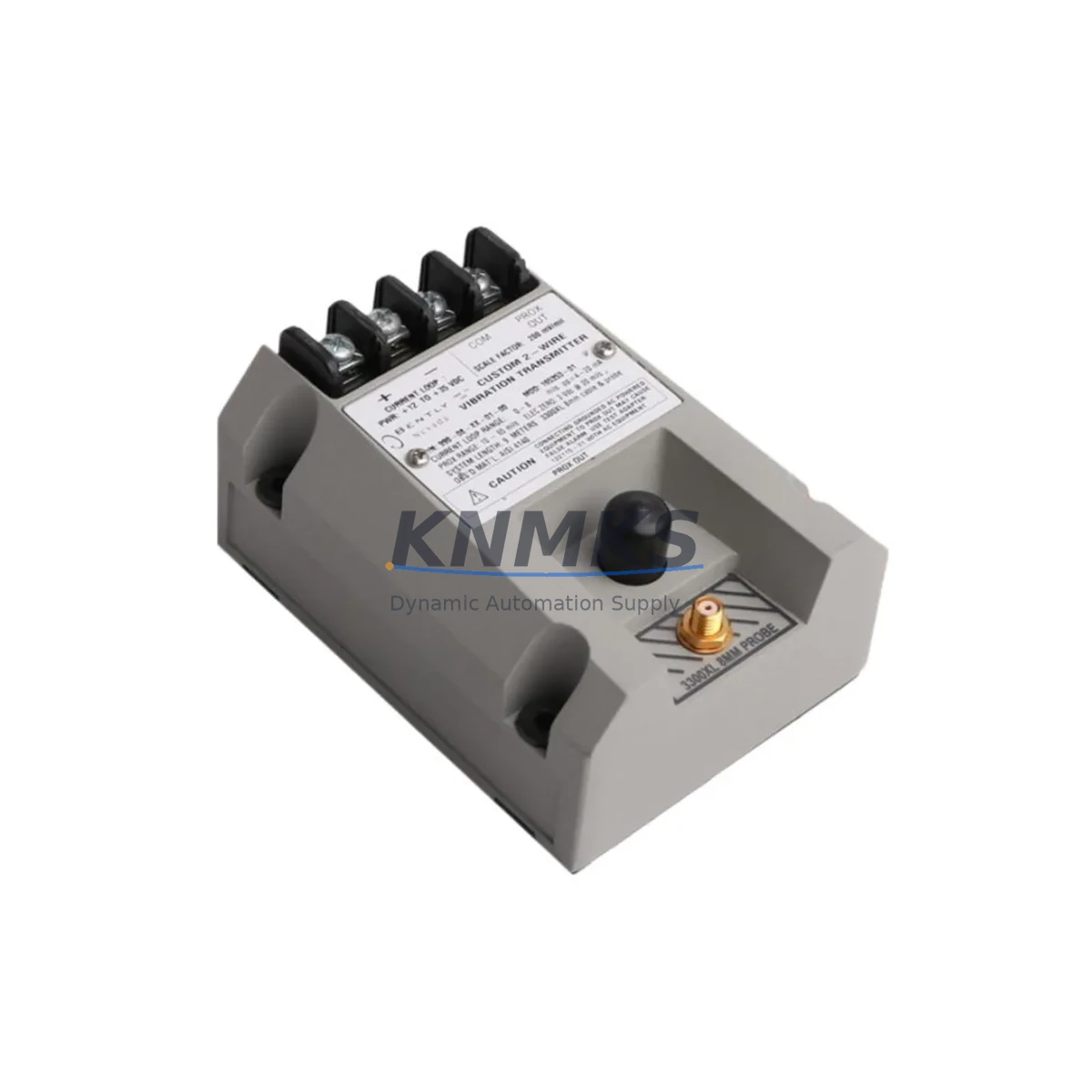
Bently Nevada 990-08-XX-01-00 Migration-Ready Vibration Transmitter: Legacy System Upgrade & Retrofit Solution
The Bently Nevada 990-08-XX-01-00 is a migration-ready vibration transmitter engineered for industrial facilities undertaking legacy control system modernization, discontinued spare parts replacement, and rotating machinery protection upgrades. As part of the Bently Nevada 990 Series platform, this transmitter delivers direct compatibility with existing Proximitor/Seismic I/O modules, 3500 Series rack infrastructure, and TDXnet communication architectures — making it the preferred drop-in solution for engineers managing brownfield retrofit projects where minimizing downtime and preserving existing wiring infrastructure are critical priorities.
Industrial facilities operating aging condition monitoring systems frequently encounter the challenge of sourcing discontinued vibration transmitters that interface reliably with installed rack hardware, existing DCS signal conditioning cards, and legacy HMI trend displays. The 990-08-XX-01-00 addresses this challenge directly by maintaining backward-compatible signal output characteristics, standard terminal block wiring configurations, and DIN rail or panel-mount installation footprints consistent with earlier 990 Series variants — allowing maintenance teams to execute module-level replacements without requiring full rack reconfiguration or PLC program modification.
Migration Compatibility Table
| Parameter | Details |
|---|---|
| SKU / Part Number | 990-08-XX-01-00 |
| Series | Bently Nevada 990 Series |
| Function | Vibration Transmitter (Seismic / Proximitor Signal Conditioning) |
| Signal Output | 4–20 mA analog, compatible with standard DCS/PLC analog input cards |
| Installation Interface | Compatible with 3500 Series rack backplane and standard terminal block wiring |
| Communication Compatibility | TDXnet, Modbus RTU (via gateway), hardwired 4–20 mA to DCS |
| Replacement Scope | Direct replacement for discontinued 990-04-XX-01-00 and 990-05-XX-01-00 variants |
| Power Supply Requirement | 24 VDC loop-powered; verify existing PSU capacity before installation |
| Installation Space | Standard 990 Series module footprint; confirm rack slot availability |
| Firmware Compatibility | Compatible with System 1 Evolution software and legacy System 1 v5.x/6.x |
| Commissioning Requirement | Gap voltage verification, transducer sensitivity calibration, alarm setpoint confirmation |
| Support terms | support terms confirmed by quotation — covers manufacturing defects and functional performance |
Retrofit Planning for Existing Automation Systems
Successful integration of the 990-08-XX-01-00 into an existing condition monitoring architecture requires systematic pre-installation planning across multiple subsystem layers. Before removing the legacy transmitter, maintenance engineers should document the existing gap voltage readings at each Proximitor probe to establish a baseline reference for post-installation verification. The 3500/42M Proximitor/Seismic Monitor module installed in the rack must be confirmed compatible with the 990-08-XX-01-00 signal conditioning output range — particularly in installations where earlier 990 Series variants were factory-configured for specific transducer sensitivities.
Terminal block wiring should be mapped against the existing field wiring schedule before disconnection. In many legacy installations, the junction box wiring between the field-mounted Proximitor probe and the transmitter input terminals follows color-coded conventions that may differ from current Bently Nevada documentation standards. Photograph and label all terminal connections prior to removal. Where the existing control cabinet houses a 3500/15 Power Supply Module, verify that the available loop power budget accommodates the 990-08-XX-01-00 current draw alongside other installed I/O modules — particularly in high-density rack configurations where multiple 3500 Series I/O modules share a common power rail.
For facilities migrating from hardwired 4–20 mA signal loops to networked condition monitoring architectures, the 990-08-XX-01-00 can serve as an interim signal source while the broader migration to System 1 Evolution networked monitoring is completed. In this configuration, the transmitter output feeds existing DCS analog input cards — such as those installed in legacy Honeywell TDC 3000 or Yokogawa CENTUM VP systems — while the parallel TDXnet communication path is established and validated. This phased approach allows facilities to maintain continuous vibration monitoring on critical rotating assets including compressors, turbines, and pumps throughout the migration period without requiring a full system cutover.
Where the retrofit scope extends beyond transmitter replacement to include I/O expansion, engineers should evaluate whether the existing 3500 Series rack has available slots for additional 3500/40M Proximitor/Seismic Monitor modules or 3500/50 Tachometer modules required to support expanded measurement point coverage. In installations where rack space is constrained, a supplementary rack assembly may be required, along with corresponding updates to the System 1 server configuration and HMI trend display groupings. Confirm that the existing Bently Nevada Data Manager or System 1 server has sufficient licensed channel capacity before adding measurement points.
Downtime Control During System Migration
Minimizing unplanned downtime during vibration transmitter replacement is a primary concern for facilities operating continuous process equipment. The 990-08-XX-01-00 is supplied pre-tested and functionally verified, allowing maintenance teams to execute a direct module swap during a planned maintenance window without requiring extended bench calibration time on-site. The recommended replacement procedure involves placing the affected monitoring channel into bypass mode within the System 1 or DCS alarm management system before disconnecting the legacy transmitter — this prevents spurious vibration alarms from triggering automatic shutdown sequences during the physical swap.
Once the 990-08-XX-01-00 is installed and terminal connections are verified against the wiring schedule, the commissioning sequence should include gap voltage measurement at the Proximitor probe, confirmation of the 4–20 mA output signal at the DCS analog input card, and verification of the vibration trend display on the operator HMI. In installations where the HMI trend historian is configured with tag-based data mapping, confirm that the engineering unit scaling and alarm setpoints associated with the replaced transmitter channel are preserved in the DCS configuration — particularly where the legacy transmitter had custom sensitivity or damping settings applied at the factory.
For critical assets where zero-downtime replacement is required, a hot-standby spare strategy using a pre-configured 990-08-XX-01-00 module allows the replacement to be completed within a single shift. All units supplied by KNMKS are functionally tested prior to shipment, with test records available upon request, reducing the risk of commissioning delays caused by infant-failure defects. The support terms confirmed by quotation cover the full post-installation operational period, providing facilities with confidence in the long-term reliability of the replacement module.
Retrofit Support FAQ
Q1: Is the 990-08-XX-01-00 a direct replacement for the discontinued 990-04-XX-01-00 and 990-05-XX-01-00?
Yes. The 990-08-XX-01-00 is designed as a functional replacement for earlier 990 Series variants including the 990-04-XX-01-00 and 990-05-XX-01-00. Terminal wiring configurations and signal output characteristics are compatible with existing rack installations. Verify transducer sensitivity settings and gap voltage specifications against your existing system documentation before installation to confirm full compatibility with your specific field configuration.
Q2: What commissioning steps are required after installation?
After physical installation, perform gap voltage verification at the Proximitor probe (typically –10 VDC ±0.5 V for standard eddy-current probes), confirm the 4–20 mA output signal at the DCS analog input terminal, verify alarm setpoints in the System 1 or DCS configuration, and restore the monitoring channel from bypass mode. Document all as-found and as-left readings in the maintenance record for future reference.
Q3: Can this transmitter be used with non-Bently Nevada DCS and PLC systems?
Yes. The 4–20 mA analog output of the 990-08-XX-01-00 is compatible with standard analog input cards used in major DCS and PLC platforms including Honeywell, Yokogawa, ABB, Siemens, and Rockwell Automation systems. Ensure that the analog input card at the receiving end is configured for the correct engineering unit range and that the loop power supply voltage is within the specified operating range for the transmitter.
Q4: What is the support terms coverage and what does KNMKS provide for inventory supply?
All 990-08-XX-01-00 units supplied by KNMKS carry a support terms confirmed by quotation covering manufacturing defects and functional performance from the date of shipment. Units are functionally tested prior to dispatch, with test documentation available upon request. KNMKS maintains stock inventory of 990 Series transmitters and related 3500 Series components to support urgent replacement requirements and planned maintenance schedules. Contact admin@knmks.com or +86 18359268345 for current stock availability and lead time confirmation.
© 2026 KNMKS. All rights reserved.
Original Source: https://knmks.com
Contact: admin@knmks.com | +86 18359268345
Product Identification
- Brand / Ecosystem
-
Bently Nevada
Bently Nevada - Model / Series
- 990-08-XX-01-00
- Product Family
- Sensors
- Availability Status
- Available on request after model and quantity confirmation
- Inquiry Type
- B2B RFQ, replacement inquiry and project spare-part request
- Pre-Quote Check
- Exact SKU, brand, series, quantity, nameplate photos and destination country are checked before quotation
System Path
Where this product fits in the KNMKS automation structure.
Specification & Inquiry Focus
- Sensor range
- Photoelectric, proximity and process sensors
- Common needs
- Output type, distance and connector
- Project support
- Machine detection and replacement inquiry
Buyer Confirmation
Information KNMKS checks before replying.
- Exact model
- 990-08-XX-01-00
- Brand / ecosystem
- Bently Nevada
- Product family
- Sensors
- Application note
- Replacement, maintenance, project build or spare-part list
- Useful photos
- Nameplate, installed unit, cabinet layout or connector side
- Delivery details
- Quantity, destination country and target schedule
Document Support
Files and notes can be confirmed during quotation.
- Product photos or nameplate confirmation when available
- Packing and delivery notes before quotation confirmation
- Support scope and delivery terms confirmed per inquiry
- Export document coordination for qualified B2B requests
Inquiry Support
- NPN/PNP, analog and digital output checking
- Connector and cable compatibility review
- Fast inquiry support for maintenance teams
What to Send Us
- Brand and exact model number: Bently Nevada 990-08-XX-01-00
- Quantity and required delivery time
- Application, replacement requirement or nameplate photo
- Destination country and shipping preference
RFQ Preparation
This is a product inquiry page built for RFQ communication.
Fast Model Check
Send this model to KNMKS for confirmation.
Include quantity, destination country and photos if this is a maintenance replacement. The inquiry will be saved with a reference number after submission.
Brand & Compatibility Note
KNMKS displays automation product information for well-known industrial brand ecosystems and compatible replacement references. Brand names are used for product identification and compatibility reference only; final availability and commercial terms are confirmed per quotation.
 Manufacturing
 Machine Tools
 Packaging
 Energy & Power

 PLCs & Controllers
 HMI & Displays
 Servo Systems
 Variable Frequency Drives