
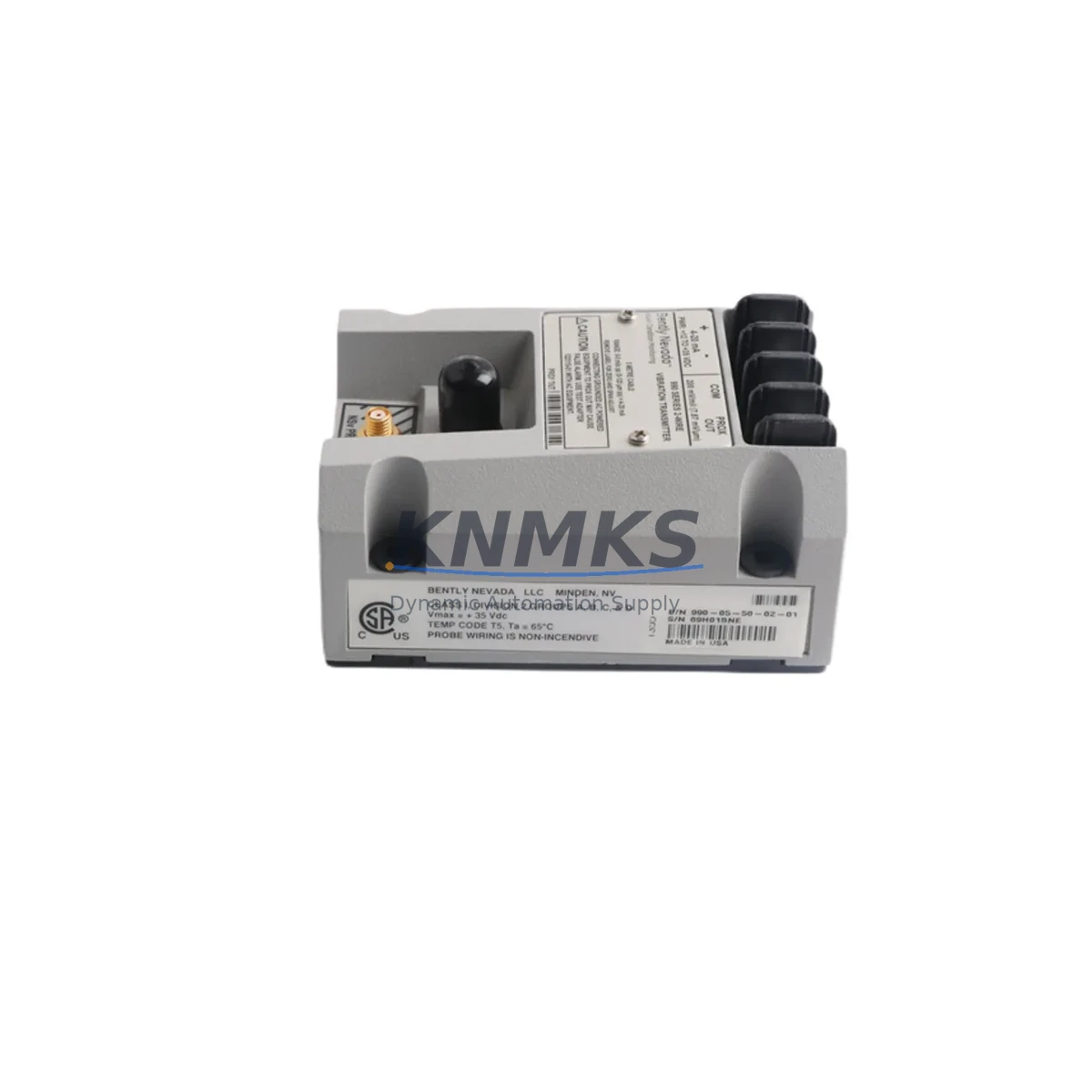
Overview
Bently Nevada 990-04-70-02-00 Migration-Ready Vibration Transmitter: Legacy System Retrofit & Compatibility Upgrade
The Bently Nevada 990-04-70-02-00 is a precision vibration transmitter engineered for continuous shaft displacement monitoring in rotating machinery protection systems. As legacy 990 Series installations approach end-of-service life, this unit serves as the verified drop-in replacement for aging or discontinued transmitter modules across turbines, compressors, pumps, and gearboxes operating under API 670-compliant machinery protection frameworks.
For maintenance engineers and reliability teams managing aging distributed control systems (DCS) or standalone machinery protection racks, the 990-04-70-02-00 addresses the most critical retrofit challenge: maintaining signal continuity and measurement accuracy without requiring full rack replacement or PLC reprogramming. The transmitter interfaces directly with existing Bently Nevada 3500 Series rack infrastructure, preserving installed wiring, terminal block assignments, and 4–20 mA output loops already mapped in the control system historian or DCS I/O card.
When planning a retrofit around this transmitter, engineers must verify power supply capacity at the rack level — the 990 Series draws from the 3500/15 Power Supply module, and any additional channel additions require confirming available headroom before commissioning. Terminal wiring from the field-mounted 3300 XL 8mm or 3300 XL 11mm proximity probes must be re-verified against the transmitter’s input impedance specifications, particularly in installations where cable runs exceed 30 meters or pass through electrically noisy environments near VFDs or high-current bus bars.
Backplane slot assignment within the 3500 Series rack is a common source of commissioning delay. The 990-04-70-02-00 occupies a standard two-slot module position; engineers should confirm slot addressing in the Rack Configuration Software (RCS) before physical installation to avoid address conflicts with adjacent 3500/42M Proximitor/Seismic Monitor modules or 3500/22M Transient Data Interface cards already active in the rack.
For sites running System 1 Evolution or older System 1 Classic software, the transmitter’s output signal maps directly to existing trend and alarm point configurations without requiring database restructuring — a significant advantage when downtime windows are constrained to planned turnaround schedules. HMI faceplate updates are typically limited to tag label revisions rather than full graphic rebuilds, reducing commissioning scope.
Communication link integrity between the 3500 rack and the plant DCS — whether via Modbus RTU, FOUNDATION Fieldbus, or hardwired 4–20 mA — should be validated using loop calibrators before the old module is removed, establishing a baseline that the replacement unit must match within ±0.5% of full-scale output. This pre-swap verification step is essential for sites where the vibration channel feeds a safety instrumented system (SIS) or emergency shutdown (ESD) logic solver.
Migration Compatibility Table
| Parameter | Details |
|---|---|
| SKU / Part Number | 990-04-70-02-00 |
| Brand / Series | Bently Nevada / 990 Series |
| Function | Vibration Transmitter (Eddy Current / Proximity) |
| Compatible Rack | Bently Nevada 3500 Series Machinery Protection Rack |
| Slot Requirement | 2-slot module position (standard 3500 rack) |
| Output Signal | 4–20 mA analog; compatible with DCS, SIS, and historian inputs |
| Communication Compatibility | Modbus RTU, FOUNDATION Fieldbus, hardwired analog loop |
| Probe Compatibility | 3300 XL 8mm, 3300 XL 11mm Proximity Probe Systems |
| Power Source | 3500/15 Power Supply Module (verify available headroom) |
| Installation Space | Standard 3500 rack form factor; no chassis modification required |
| Firmware / Software | Compatible with Rack Configuration Software (RCS); System 1 Evolution & Classic |
| Replacement Path | Direct drop-in for legacy 990 Series transmitter modules |
| Commissioning Focus | Slot address verification, loop calibration, HMI tag update |
| Support terms | support terms confirmed by quotation — tested and verified before shipment |
Retrofit Planning for Existing Automation Systems
A successful retrofit centered on the 990-04-70-02-00 typically involves coordinating several interdependent components within the same machinery protection cabinet. The 3500/15 Power Supply must be assessed first — insufficient power margin is the leading cause of post-retrofit instability when additional monitoring channels are added to an existing rack. In parallel, the field wiring from proximity probe extension cables should be inspected for insulation degradation, particularly in high-temperature or high-vibration environments where cable jackets may have hardened over years of service.
The 3500/42M Proximitor/Seismic Monitor is frequently present in the same rack and shares the backplane communication bus. Engineers should confirm that adding or replacing the 990-04-70-02-00 does not alter the polling sequence or interrupt the monitor’s alarm relay outputs during the hot-swap window. Where the rack also includes a 3500/22M Transient Data Interface, the waveform capture configuration should be backed up before any module change to prevent loss of transient event history.
For sites integrating vibration data into a broader DCS environment — such as a Honeywell Experion PKS or Emerson DeltaV platform — the 4–20 mA signal from the 990-04-70-02-00 feeds into analog input cards that may require re-ranging if the previous transmitter had a different span configuration. Signal isolators, such as those used between the 3500 rack output and the DCS marshalling cabinet, should be verified for loop impedance compatibility to avoid signal clipping at high-vibration alarm thresholds.
In control cabinets where space is constrained, the standard 3500 rack form factor of the 990-04-70-02-00 eliminates the need for bracket modifications or DIN rail adapters. However, engineers should confirm that adjacent modules — including any 3500/32 4-Channel Relay Module used for alarm and trip output — have adequate clearance for connector access during commissioning. Programming cable access to the rack’s front-panel RS-232 or Ethernet port should also be confirmed before the maintenance window begins.
Downtime Control During System Migration
Minimizing unplanned downtime during a 990-04-70-02-00 swap requires a structured pre-outage preparation protocol. Before the maintenance window opens, the existing module’s configuration should be exported from the Rack Configuration Software and stored offline. This configuration file captures channel scaling, alarm setpoints, gap voltage references, and relay assignments — all of which must be re-applied to the replacement module before it is inserted into the rack.
Where the vibration channel is wired into a safety instrumented system, the SIS logic solver must be placed in bypass mode through the approved management-of-change (MOC) process before the transmitter is removed. Failure to follow this sequence risks spurious trip activation, which in rotating machinery applications can trigger unplanned unit shutdowns with significant production impact.
The physical swap of the 990-04-70-02-00 is typically completed within 15–30 minutes once the rack slot is confirmed and the replacement module is pre-configured. Post-installation verification includes gap voltage measurement at the proximitor output, 4–20 mA loop check from the transmitter to the DCS input card, alarm setpoint confirmation in System 1, and a functional test of the relay output to the ESD panel. Documenting each step in the site’s maintenance management system (CMMS) ensures traceability and supports future audit requirements.
For sites with redundant monitoring channels, the retrofit can be staged — replacing one channel at a time while the parallel channel remains active — further reducing exposure to unmonitored machinery operation. This approach is particularly effective in critical compressor or turbine applications where continuous vibration monitoring is a permit-to-operate requirement.
Retrofit Support FAQ
Q1: Is the 990-04-70-02-00 a direct replacement for all legacy 990 Series transmitter variants?
The 990-04-70-02-00 is designed as a drop-in replacement for the standard 990 Series vibration transmitter configuration used in 3500 rack systems. Before ordering, confirm the probe type (8mm or 11mm), cable length, and gap voltage range of the existing installation to ensure full signal compatibility. Our technical team can assist with cross-reference verification based on your existing part number and site configuration.
Q2: What pre-shipment testing is performed on this unit?
Each 990-04-70-02-00 unit is functionally tested prior to shipment, including output signal verification, power consumption check, and communication interface validation. Units are shipped with a test report and are covered by a support terms confirmed by quotation from the date of delivery. Stock is maintained for fast dispatch to minimize lead time impact on planned maintenance schedules.
Q3: Can this transmitter be commissioned without the Rack Configuration Software?
Rack Configuration Software (RCS) is strongly recommended for full configuration and alarm setpoint programming. However, if the replacement module is pre-configured to match the outgoing unit’s settings — exported before removal — commissioning can proceed with minimal software interaction, limited to gap voltage verification and loop check. On-site firmware version compatibility with the existing 3500 rack should be confirmed before installation.
Q4: What is the support terms and return policy?
All units carry a support terms confirmed by quotation covering manufacturing defects and functional failures under normal operating conditions. Units are inspected and tested before shipment. For support requests or technical support during commissioning, contact our sales team directly with your order reference and site configuration details.
© 2026 KNMKS. All rights reserved.
Original Source: https://knmks.com
Contact: admin@knmks.com | +86 18359268345
Product Identification
- Brand / Ecosystem
-
Bently Nevada
Bently Nevada - Model / Series
- 990-04-70-02-00
- Product Family
- Sensors
- Availability Status
- Available on request after model and quantity confirmation
- Inquiry Type
- B2B RFQ, replacement inquiry and project spare-part request
- Pre-Quote Check
- Exact SKU, brand, series, quantity, nameplate photos and destination country are checked before quotation
System Path
Where this product fits in the KNMKS automation structure.
Specification & Inquiry Focus
- Sensor range
- Photoelectric, proximity and process sensors
- Common needs
- Output type, distance and connector
- Project support
- Machine detection and replacement inquiry
Buyer Confirmation
Information KNMKS checks before replying.
- Exact model
- 990-04-70-02-00
- Brand / ecosystem
- Bently Nevada
- Product family
- Sensors
- Application note
- Replacement, maintenance, project build or spare-part list
- Useful photos
- Nameplate, installed unit, cabinet layout or connector side
- Delivery details
- Quantity, destination country and target schedule
Document Support
Files and notes can be confirmed during quotation.
- Product photos or nameplate confirmation when available
- Packing and delivery notes before quotation confirmation
- Support scope and delivery terms confirmed per inquiry
- Export document coordination for qualified B2B requests
Inquiry Support
- NPN/PNP, analog and digital output checking
- Connector and cable compatibility review
- Fast inquiry support for maintenance teams
What to Send Us
- Brand and exact model number: Bently Nevada 990-04-70-02-00
- Quantity and required delivery time
- Application, replacement requirement or nameplate photo
- Destination country and shipping preference
RFQ Preparation
This is a product inquiry page built for RFQ communication.
Fast Model Check
Send this model to KNMKS for confirmation.
Include quantity, destination country and photos if this is a maintenance replacement. The inquiry will be saved with a reference number after submission.
Brand & Compatibility Note
KNMKS displays automation product information for well-known industrial brand ecosystems and compatible replacement references. Brand names are used for product identification and compatibility reference only; final availability and commercial terms are confirmed per quotation.
 Manufacturing
 Machine Tools
 Packaging
 Energy & Power

 PLCs & Controllers
 HMI & Displays
 Servo Systems
 Variable Frequency Drives