
Overview
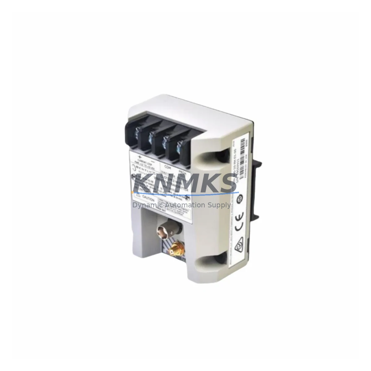
Bently Nevada 990-04-50-01-01 Spare Part for Factory Uptime
The Bently Nevada 990-04-50-01-01 is a loop-powered, 4–20 mA vibration transmitter engineered for continuous machinery health monitoring in rotating equipment applications. As a maintenance-proven spare part, it is widely deployed in turbines, compressors, pumps, and motors across oil & gas, power generation, petrochemical, and heavy manufacturing facilities. Holding a verified replacement unit in your spare parts inventory is the single most effective measure to minimize unplanned downtime when a transmitter fault is detected during routine inspection or emergency shutdown analysis.
At KNMKS, every 990-04-50-01-01 unit is sourced from authorized supply channels, subjected to pre-shipment functional verification, and dispatched with a support terms confirmed by quotation. Multi-region stock ensures rapid global fulfillment for both scheduled outage windows and emergency callouts. Whether you are executing a planned annual overhaul or responding to a critical vibration alarm at 02:00, a tested replacement unit can be on-site within your required lead time.
Spare Maintenance Table
| Parameter | Specification |
|---|---|
| Part Number | 990-04-50-01-01 |
| Brand | Bently Nevada |
| Series | 990 Series |
| Product Type | Vibration Transmitter |
| Output Signal | 4–20 mA (loop-powered) |
| Measurement | Velocity / Vibration (RMS or Peak) |
| Supply Voltage | 18–30 VDC (loop supply) |
| Frequency Range | 10–1000 Hz (typical 990 Series) |
| Output Load | ≤ 600 Ω at 24 VDC |
| Enclosure Rating | IP65 / NEMA 4 |
| Operating Temperature | -40°C to +85°C |
| Mounting | Stud mount / adhesive pad compatible |
| Connector | 2-wire terminal / M12 (series dependent) |
| Compatibility | Bently Nevada 3500 Rack, System 1 Software, DCS/PLC 4–20 mA AI cards |
| Origin | United States |
| Support terms | 12 Months (KNMKS) |
| Pre-Shipment Test | Yes — functional verification before dispatch |
| Typical Applications | Turbines, Compressors, Pumps, Motors, Fans |
| Maintenance Interval | Inspect every 12 months or per OEM schedule |
Maintenance Planning for Continuous Operation
When replacing the 990-04-50-01-01 vibration transmitter during a planned outage or emergency callout, maintenance engineers should treat the replacement as an opportunity to audit the entire vibration monitoring loop and adjacent control cabinet components. A transmitter fault rarely occurs in isolation — signal degradation, wiring fatigue, and power supply instability are common contributing factors that, if left unaddressed, will shorten the service life of the new unit.
Begin with the loop power supply: verify that the 24 VDC rail feeding the transmitter is within tolerance (18–30 VDC) and free of ripple. A degraded DIN-rail power supply or shared bus with high-inrush loads can cause intermittent 4–20 mA signal errors that mimic transmitter failure. Next, inspect the field wiring and terminal blocks — corroded or loose terminals on the marshalling cabinet are a leading cause of signal drift in vibration monitoring loops. Replace any discolored or pitted terminals before reinstalling the transmitter.
Check the Bently Nevada 3500 Series rack input card (typically a 3500/42M or 3500/45 monitor module) for firmware currency and channel calibration. A miscalibrated monitor card will produce false alarms even with a correctly functioning 990-04-50-01-01. If the rack has been in service for more than five years, inspect the 3500 rack backplane and power supply module (3500/15 or 3500/20) for capacitor aging and connector oxidation.
For installations where the transmitter signal is routed through a signal isolator or barrier (common in Zone 1/Zone 2 hazardous area installations), verify that the isolator’s input impedance and loop burden are compatible with the 990-04-50-01-01’s output drive capability. Zener barriers and galvanic isolators from the same vintage as the transmitter should be replaced proactively during the same maintenance window.
Finally, review the System 1 software configuration to confirm that the channel tag, engineering unit scaling (mm/s or in/s), and alarm setpoints are correctly mapped to the replacement unit’s output range. Mismatched scaling is a common post-replacement issue that generates nuisance alarms and can mask genuine machinery faults during the post-maintenance run-up period.
Site Replacement Workflow
Step 1 — Isolation & Permit: Obtain a Permit to Work (PTW) and isolate the machinery. De-energize the loop supply at the marshalling cabinet and confirm zero energy with a calibrated multimeter before disconnecting the transmitter.
Step 2 — Document Existing Configuration: Record the existing wiring polarity, terminal numbers, cable routing, and any cable gland torque specifications. Photograph the installation before removal. Confirm the replacement 990-04-50-01-01 matches the original unit’s suffix codes (mounting style, connector type, cable length if integral).
Step 3 — Mechanical Installation: Clean the mounting surface and apply the correct stud torque per the Bently Nevada installation manual. Avoid over-torquing, which can introduce mechanical stress and affect frequency response. For adhesive-mount applications, use the OEM-specified adhesive and allow full cure time before energizing.
Step 4 — Electrical Reconnection: Reconnect wiring per the original documentation. Verify loop continuity and insulation resistance before re-energizing. Apply loop power and confirm the transmitter outputs a valid 4–20 mA signal at the 3500 rack input card.
Step 5 — Functional Verification: Use a calibrated vibration reference source or the machinery’s known baseline vibration level to verify that the replacement unit’s output tracks correctly through the full measurement range. Confirm alarm setpoints are active and System 1 is logging data from the new channel.
Step 6 — Return to Service & Documentation: Update the maintenance management system (CMMS) with the replacement date, new unit serial number, and next inspection interval. Retain the removed unit for failure analysis if root cause investigation is required.
Spare Parts Support FAQ
Q1: Is the 990-04-50-01-01 a direct drop-in replacement for older 990 Series transmitters?
Yes. The 990-04-50-01-01 is designed as a direct mechanical and electrical replacement within the 990 Series product family. It maintains the same 4–20 mA output interface, mounting footprint, and connector pinout as earlier 990 Series variants, ensuring compatibility with existing Bently Nevada 3500 rack input cards and DCS/PLC analog input channels without requiring reconfiguration.
Q2: What pre-shipment testing does KNMKS perform before dispatching the unit?
Every 990-04-50-01-01 unit undergoes functional verification prior to dispatch. Testing includes loop-powered output linearity check across the 4–20 mA range, insulation resistance measurement, and connector integrity inspection. Units that do not meet specification are quarantined and not shipped. A support terms confirmed by quotation cover all units from the date of delivery.
Q3: How should procurement engineers manage long-term supply risk for the 990-04-50-01-01?
Given the 990 Series’ installed base across critical rotating equipment, procurement teams should maintain a minimum of one to two replacement units per monitored machine train in their on-site spare parts inventory. KNMKS offers long-term supply agreements and multi-region stock to support annual maintenance budgets and emergency callout requirements. Early engagement with KNMKS for annual volume commitments reduces lead time risk and unit cost.
Q4: Can the 990-04-50-01-01 be used with third-party DCS or PLC systems outside the Bently Nevada 3500 rack?
Yes. The 990-04-50-01-01’s standard 4–20 mA loop-powered output is compatible with any DCS or PLC analog input card that accepts a 2-wire 4–20 mA signal with a loop supply of 18–30 VDC. Compatibility has been confirmed with Emerson DeltaV, Honeywell Experion PKS, Yokogawa CENTUM VP, and Siemens SIMATIC S7-300/400 analog input modules. Verify the input card’s loop burden resistance is within the transmitter’s specified load range (≤ 600 Ω at 24 VDC) before installation.
© 2026 KNMKS. All rights reserved.
Original Source: https://knmks.com
Contact: admin@knmks.com | +86 18359268345
Product Identification
- Brand / Ecosystem
-
Bently Nevada
Bently Nevada - Model / Series
- 990-04-50-01-01
- Product Family
- Sensors
- Availability Status
- Available on request after model and quantity confirmation
- Inquiry Type
- B2B RFQ, replacement inquiry and project spare-part request
- Pre-Quote Check
- Exact SKU, brand, series, quantity, nameplate photos and destination country are checked before quotation
System Path
Where this product fits in the KNMKS automation structure.
Specification & Inquiry Focus
- Sensor range
- Photoelectric, proximity and process sensors
- Common needs
- Output type, distance and connector
- Project support
- Machine detection and replacement inquiry
Buyer Confirmation
Information KNMKS checks before replying.
- Exact model
- 990-04-50-01-01
- Brand / ecosystem
- Bently Nevada
- Product family
- Sensors
- Application note
- Replacement, maintenance, project build or spare-part list
- Useful photos
- Nameplate, installed unit, cabinet layout or connector side
- Delivery details
- Quantity, destination country and target schedule
Document Support
Files and notes can be confirmed during quotation.
- Product photos or nameplate confirmation when available
- Packing and delivery notes before quotation confirmation
- Support scope and delivery terms confirmed per inquiry
- Export document coordination for qualified B2B requests
Inquiry Support
- NPN/PNP, analog and digital output checking
- Connector and cable compatibility review
- Fast inquiry support for maintenance teams
What to Send Us
- Brand and exact model number: Bently Nevada 990-04-50-01-01
- Quantity and required delivery time
- Application, replacement requirement or nameplate photo
- Destination country and shipping preference
RFQ Preparation
This is a product inquiry page built for RFQ communication.
Fast Model Check
Send this model to KNMKS for confirmation.
Include quantity, destination country and photos if this is a maintenance replacement. The inquiry will be saved with a reference number after submission.
Brand & Compatibility Note
KNMKS displays automation product information for well-known industrial brand ecosystems and compatible replacement references. Brand names are used for product identification and compatibility reference only; final availability and commercial terms are confirmed per quotation.
 Manufacturing
 Machine Tools
 Packaging
 Energy & Power

 PLCs & Controllers
 HMI & Displays
 Servo Systems
 Variable Frequency Drives