
Overview
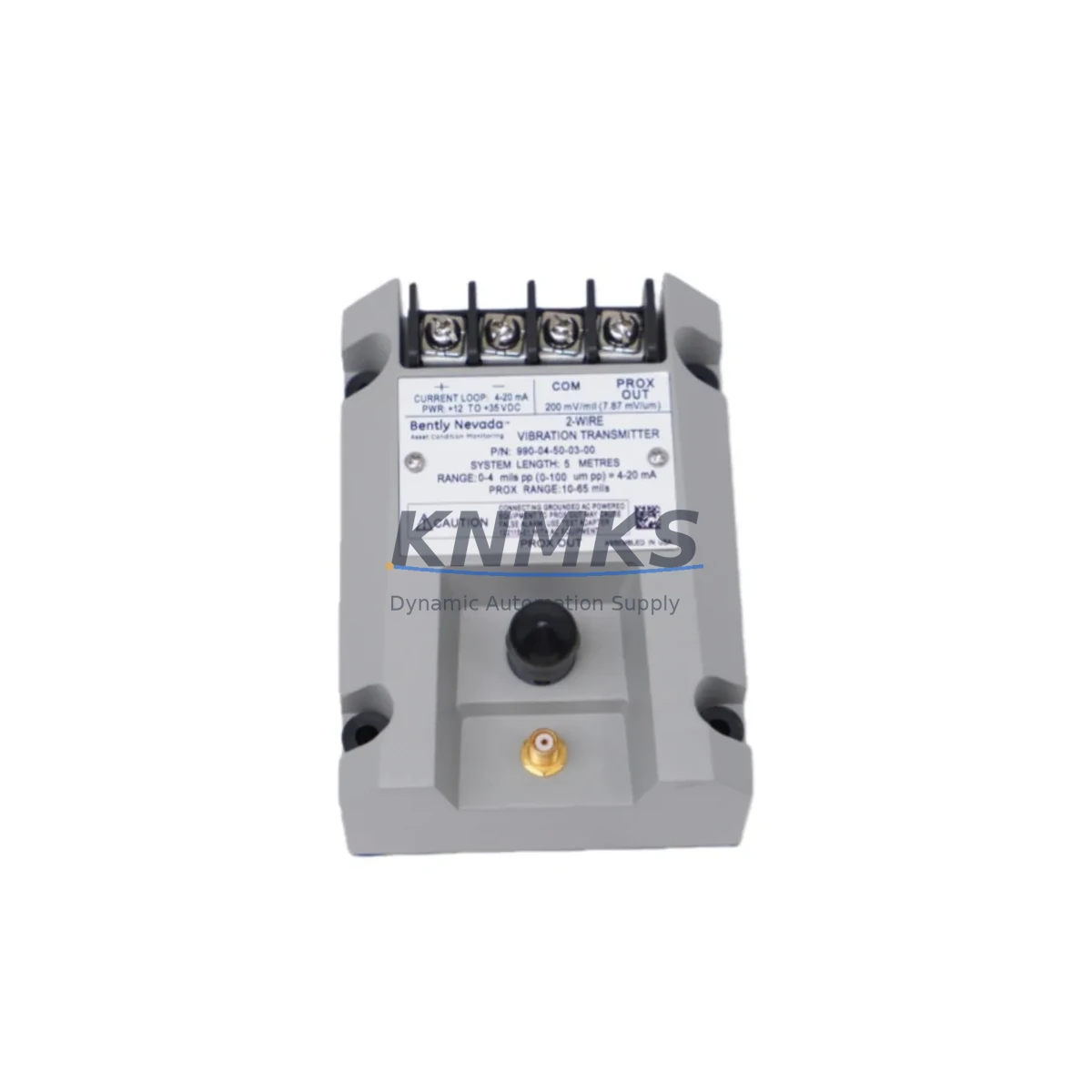
Bently Nevada 990-04-07-01-05 Migration-Ready Vibration Transmitter: Legacy System Retrofit & Upgrade
The Bently Nevada 990-04-07-01-05 is a migration-ready vibration transmitter engineered for direct replacement and compatibility upgrade within the Bently Nevada 990 Series platform. Designed for industrial facilities operating legacy rotating machinery protection systems, this module supports seamless integration into existing control cabinets, DCS architectures, and safety instrumented systems without requiring full panel redesign. Whether you are managing a planned shutdown retrofit or an emergency spare replacement, the 990-04-07-01-05 delivers the signal integrity, mechanical compatibility, and firmware alignment required to restore system continuity with minimal downtime.
In petrochemical, power generation, and heavy manufacturing environments, the 990 Series vibration monitoring platform remains widely deployed on critical rotating assets including compressors, turbines, pumps, and fans. As original equipment manufacturers phase out legacy modules, sourcing verified replacement units becomes a primary operational risk. The 990-04-07-01-05 addresses this directly — providing a tested, in-stock alternative with documented compatibility for the 990 Series rack architecture, including verified terminal block pinout, 4-20mA analog output signal range, and standard DIN rail or panel mounting dimensions.
Before installation, engineers should confirm power supply capacity at the existing rack. The 990 Series backplane typically distributes 24VDC to each module slot; verify that the existing power supply module — such as the 990-01-XX-01-00 series power conditioner — can support the additional load if multiple modules are being replaced simultaneously. Terminal wiring should be cross-referenced against the original loop drawing: the 990-04-07-01-05 uses a standard 3-wire connection for the proximity probe input, and any deviation in shield grounding practice from the original installation can introduce noise into the vibration signal chain.
Backplane interface compatibility is a critical checkpoint. The 990 Series uses a proprietary edge connector that must be inspected for pin corrosion or mechanical damage before seating the replacement module. Module address configuration — typically set via DIP switch or rotary selector on the front panel — must match the original channel assignment to ensure the host system, whether a System 1 Evolution software platform or a third-party DCS via Modbus RTU or 4-20mA hardwire, correctly maps the vibration channel to the corresponding asset tag.
Program logic compatibility should be validated in the DCS or PLC prior to hot-swap. If the facility uses a Rockwell Automation ControlLogix or Allen-Bradley PLC5 as the supervisory controller receiving 4-20mA signals from the 990 rack, confirm that the analog input module scaling parameters — engineering units, alarm setpoints, and trip thresholds — remain unchanged after the module swap. HMI screen tag bindings in FactoryTalk View or Wonderware InTouch should also be verified to ensure vibration trend displays and alarm banners continue to reference the correct I/O address.
Communication link integrity is especially important in facilities where the 990 rack communicates upstream via a Bently Nevada 3500/92 communication gateway or a dedicated Ethernet/IP adapter. After module replacement, perform a full communication health check to confirm that the rack is transmitting live vibration data to the plant historian or condition monitoring server without packet loss or timeout errors.
Installation space should be confirmed before ordering. The 990-04-07-01-05 occupies a single slot in the standard 990 Series 19-inch rack chassis. If the target slot is adjacent to a high-heat module such as a keyphasor conditioner or a power supply, ensure adequate ventilation clearance per the original rack layout drawing. Firmware version alignment between the replacement module and the existing rack controller firmware should be confirmed with the commissioning engineer — mismatched firmware revisions can cause initialization failures or reduced diagnostic capability.
All units are pre-tested prior to shipment, including functional output signal verification and insulation resistance checks. Stock is maintained for immediate dispatch, supporting both planned maintenance windows and unplanned outage recovery scenarios. Each unit is covered by a support terms confirmed by quotation from the date of shipment.
Migration Compatibility Table
| Parameter | 990-04-07-01-05 Specification | Retrofit Notes |
|---|---|---|
| Output Signal | 4-20mA analog | Compatible with standard DCS analog input cards |
| Input Type | Proximity probe (3-wire) | Verify shield grounding per original loop drawing |
| Power Supply | 24VDC via 990 Series backplane | Confirm rack PSU capacity before multi-module swap |
| Mounting | Single-slot, 990 Series 19″ rack chassis | Confirm slot clearance and ventilation |
| Communication | 4-20mA hardwire / Modbus RTU (via gateway) | Verify gateway firmware and tag mapping post-swap |
| Module Address | DIP switch / rotary selector configurable | Match original channel assignment before power-on |
| Replacement Target | 990 Series legacy vibration transmitter modules | Direct slot-for-slot replacement in 990 rack |
| Support terms | 12 months from shipment | Covers functional failure under normal operating conditions |
Retrofit Planning for Existing Automation Systems
A successful retrofit of the 990-04-07-01-05 into an existing automation system requires a structured pre-outage planning process. Begin by auditing the full 990 Series rack population: identify all installed modules by slot position, including any 990-01-XX-01-00 power supply modules, 990-05-XX-01-00 keyphasor input modules, and 990-06-XX-01-00 relay output modules. This audit establishes the baseline configuration against which the post-retrofit system will be validated.
Terminal block wiring documentation is essential. Pull the original as-built drawings for the control cabinet and verify that each field cable termination — proximity probe cable, power feed, and signal output — is labeled and traceable. If the facility uses a Bently Nevada 3500 Series rack in parallel for comparison or redundancy, cross-reference the channel configuration to ensure alarm setpoints are consistent across both platforms during the transition period.
I/O mapping should be completed before the maintenance window opens. If the supervisory PLC — for example, a Siemens S7-300 or a Honeywell Experion PKS controller — receives the 4-20mA vibration signal via a dedicated analog input module, confirm that the input scaling, filter time constant, and alarm deadband settings are documented and will be restored identically after the module swap. Any changes to these parameters during the retrofit window can trigger nuisance alarms or mask genuine vibration events during the post-restart monitoring period.
Signal isolators installed between the 990 rack output and the DCS input should be inspected and tested as part of the retrofit scope. Aging signal isolators can introduce offset errors that are incorrectly attributed to the replacement module. Similarly, programming cables used for firmware verification or module configuration — such as a standard RS-232 to USB adapter compatible with the Bently Nevada configuration software — should be prepared and tested before the outage begins to avoid delays during the commissioning phase.
Downtime Control During System Migration
Minimizing downtime during a 990 Series module replacement requires pre-staging all replacement hardware, tools, and documentation before the maintenance window begins. The 990-04-07-01-05 should be bench-tested for output signal integrity using a calibrated loop calibrator before it enters the control cabinet, confirming that the 4-20mA output tracks correctly across the full measurement range.
To protect original program logic, export and archive the current DCS or PLC configuration — including all analog input scaling parameters, alarm setpoints, and interlock logic — before any hardware is disturbed. If the facility uses a System 1 Evolution condition monitoring platform, export the current machine train configuration and trend data as a backup. This ensures that if the post-retrofit commissioning reveals unexpected behavior, the original configuration can be restored without relying on memory or informal documentation.
Field control continuity can be maintained during the module swap by placing the affected vibration channel in bypass mode at the DCS or safety system level, preventing spurious trips during the period when the channel is unpowered. Coordinate with the control room operator to confirm bypass status before disconnecting the field wiring, and restore the channel to active monitoring only after the replacement module has been powered, configured, and verified to be transmitting a valid signal within the expected engineering unit range.
Post-replacement commissioning should include a full functional test: apply a known vibration stimulus or use a signal simulator to verify that the 990-04-07-01-05 output tracks correctly, that the DCS receives and displays the correct engineering unit value, and that alarm and trip setpoints activate at the configured thresholds. Document the commissioning results and retain them as part of the equipment maintenance record.
Retrofit Support FAQ
Q: Is the 990-04-07-01-05 a direct replacement for the original Bently Nevada 990 Series vibration transmitter in the same rack slot?
A: Yes. The 990-04-07-01-05 is designed for slot-for-slot replacement within the standard 990 Series 19-inch rack chassis. Terminal pinout, backplane connector, and module address configuration are compatible with the original 990 Series architecture. Verify DIP switch or rotary address settings match the original channel assignment before powering the module.
Q: What commissioning steps are required after installing the replacement module?
A: After seating the module and restoring terminal wiring, power the rack and confirm the module initializes without fault indicators. Verify the 4-20mA output signal at the DCS analog input using a calibrated loop calibrator. Confirm that the DCS or PLC displays the correct engineering unit value and that alarm setpoints activate correctly. Remove any bypass conditions applied during the swap and monitor the channel for a minimum of one full operating cycle before closing the work order.
Q: How do I verify wiring compatibility before installation?
A: Pull the original as-built loop drawing for the affected vibration channel. Confirm that the proximity probe cable — including shield, positive, and negative conductors — is terminated at the correct terminal block positions per the 990-04-07-01-05 wiring diagram. Verify shield grounding practice matches the original installation to avoid introducing noise into the vibration signal. If the original drawing is unavailable, contact our technical support team for wiring guidance specific to your rack configuration.
Q: What are the inventory availability and support terms terms?
A: The 990-04-07-01-05 is maintained availability confirmed by RFQ for immediate dispatch, supporting both planned maintenance schedules and emergency outage recovery. Each unit undergoes pre-shipment functional testing including output signal verification and insulation resistance checks. A support terms confirmed by quotation is provided from the date of shipment, covering functional failure under normal operating conditions. Contact admin@knmks.com or +86 18359268345 for current stock status and lead time confirmation.
© 2026 KNMKS. All rights reserved.
Original Source: https://knmks.com
Contact: admin@knmks.com | +86 18359268345
Product Identification
- Brand / Ecosystem
-
Bently Nevada
Bently Nevada - Model / Series
- 990-04-07-01-05
- Product Family
- Sensors
- Availability Status
- Available on request after model and quantity confirmation
- Inquiry Type
- B2B RFQ, replacement inquiry and project spare-part request
- Pre-Quote Check
- Exact SKU, brand, series, quantity, nameplate photos and destination country are checked before quotation
System Path
Where this product fits in the KNMKS automation structure.
Specification & Inquiry Focus
- Sensor range
- Photoelectric, proximity and process sensors
- Common needs
- Output type, distance and connector
- Project support
- Machine detection and replacement inquiry
Buyer Confirmation
Information KNMKS checks before replying.
- Exact model
- 990-04-07-01-05
- Brand / ecosystem
- Bently Nevada
- Product family
- Sensors
- Application note
- Replacement, maintenance, project build or spare-part list
- Useful photos
- Nameplate, installed unit, cabinet layout or connector side
- Delivery details
- Quantity, destination country and target schedule
Document Support
Files and notes can be confirmed during quotation.
- Product photos or nameplate confirmation when available
- Packing and delivery notes before quotation confirmation
- Support scope and delivery terms confirmed per inquiry
- Export document coordination for qualified B2B requests
Inquiry Support
- NPN/PNP, analog and digital output checking
- Connector and cable compatibility review
- Fast inquiry support for maintenance teams
What to Send Us
- Brand and exact model number: Bently Nevada 990-04-07-01-05
- Quantity and required delivery time
- Application, replacement requirement or nameplate photo
- Destination country and shipping preference
RFQ Preparation
This is a product inquiry page built for RFQ communication.
Fast Model Check
Send this model to KNMKS for confirmation.
Include quantity, destination country and photos if this is a maintenance replacement. The inquiry will be saved with a reference number after submission.
Brand & Compatibility Note
KNMKS displays automation product information for well-known industrial brand ecosystems and compatible replacement references. Brand names are used for product identification and compatibility reference only; final availability and commercial terms are confirmed per quotation.
 Manufacturing
 Machine Tools
 Packaging
 Energy & Power

 PLCs & Controllers
 HMI & Displays
 Servo Systems
 Variable Frequency Drives