
Overview
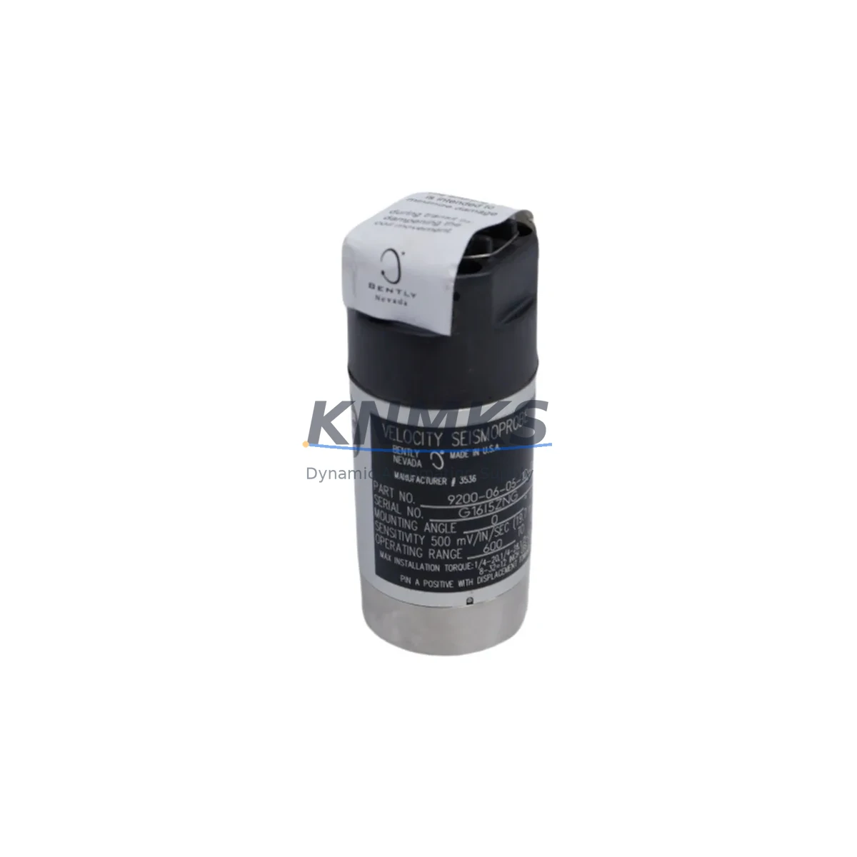
Bently Nevada 9200-06-5-05-00 Migration-Ready Proximity Transducer for Legacy Control Systems
The Bently Nevada 9200-06-5-05-00 is a 5-metre extension cable proximity transducer system designed for continuous vibration monitoring in rotating machinery applications. As legacy 9200 Series installations approach end-of-life or face discontinued spare parts availability, this migration-ready unit provides a verified drop-in replacement path for facilities operating Bently Nevada 3300, 7200, and 3500 Series monitoring platforms. Whether you are managing a planned outage, responding to an unplanned failure, or executing a phased control system upgrade, the 9200-06-5-05-00 is stocked and ready for immediate dispatch with a support terms confirmed by quotation covering all components.
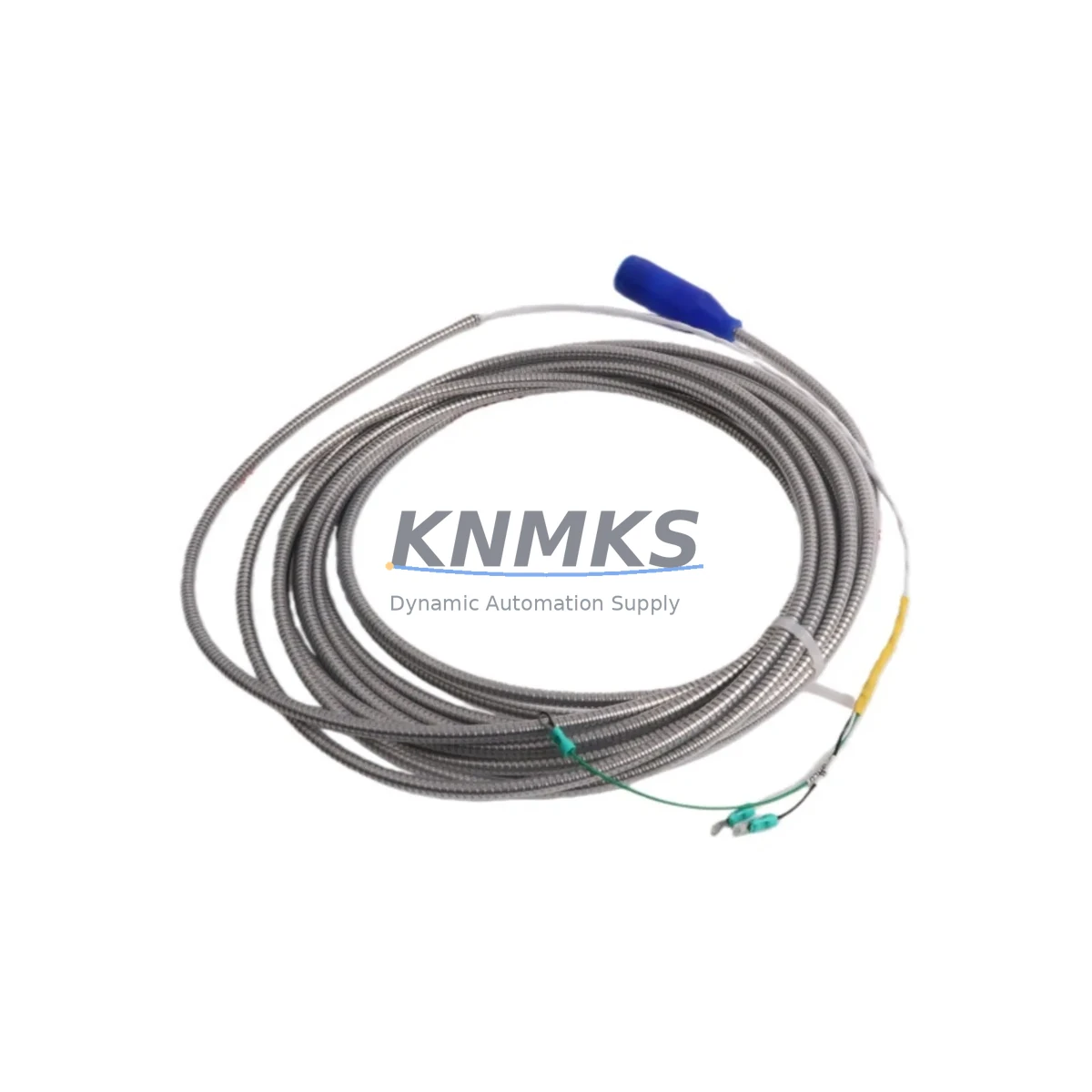
The 9200 Series proximity transducer system consists of three matched components: the probe, the extension cable, and the proximitor (driver). The 9200-06-5-05-00 designation specifies a 6 mm probe tip diameter with a 5-metre extension cable and a standard output range of 0 to 5 mm gap. When replacing a failed or discontinued unit, engineers must confirm that the replacement proximitor — such as the 3300 XL 8mm or the 7200 Series proximitor — is calibrated to match the transducer system’s sensitivity factor (typically 7.87 V/mm or 200 mV/mil). Mismatched sensitivity factors between the probe, cable, and proximitor are the most common source of calibration errors during retrofit installations.
Before committing to a replacement order, maintenance teams should verify the existing gap voltage at the monitor input card. The Bently Nevada 3500/42M Proximitor/Seismic Monitor and the 3500/40M Proximitor Monitor are the most common rack-mounted receivers for 9200 Series transducer outputs. If the existing rack uses a 3500/42M, confirm that the input channel is configured for the correct transducer type and that the OK relay setpoints are aligned with the new transducer’s linear range. For facilities still operating the older 3300 Series rack, a rack-level migration to the 3500 Series may be advisable to ensure long-term firmware and spare parts support.
Migration Compatibility Table
| Parameter | 9200-06-5-05-00 Specification | Retrofit Notes |
|---|---|---|
| Probe Tip Diameter | 6 mm | Confirm existing probe bore and bracket clearance before installation |
| Extension Cable Length | 5 metres | Match to existing cable routing; do not splice or extend |
| Output Gap Range | 0 – 5 mm | Verify monitor input card accepts this range; reconfigure setpoints if needed |
| Sensitivity Factor | 7.87 V/mm (200 mV/mil) | Must match proximitor calibration; confirm with 3300/7200/3500 Series proximitor datasheet |
| Supply Voltage | -24 VDC (nominal) | Verify power supply rail at terminal block; check for voltage drop across long cable runs |
| Compatible Monitor Racks | 3300, 3500, 7200 Series | Confirm slot assignment and channel configuration in rack manager software |
| Communication Protocol | Analogue (4–20 mA / voltage output) | No protocol migration required; signal conditioning handled at monitor card level |
| Installation Space | Standard 6 mm probe bracket | Confirm radial clearance and axial position relative to shaft target area |
| Firmware Compatibility | N/A (passive transducer) | Firmware update may be required on 3500 Series monitor card after channel reconfiguration |
| Support terms | 12 Months | Covers probe, extension cable, and connector assembly; excludes physical damage |
Retrofit Planning for Existing Automation Systems
A successful retrofit of the 9200-06-5-05-00 begins well before the maintenance window opens. The first step is a full audit of the existing transducer loop: trace the signal path from the probe tip through the extension cable to the proximitor, then from the proximitor output to the monitor input card terminal block. Document the terminal numbers, wire colours, and shield grounding points. In many legacy installations, the shield drain wire is grounded at one end only — typically at the proximitor enclosure — and re-grounding at both ends during a replacement can introduce ground loop noise that triggers false OK relay trips.
For facilities running the Bently Nevada 3500 Series rack, the System 1 configuration software should be used to export the existing channel configuration before any hardware is disturbed. This export preserves alert and danger setpoints, transducer type assignments, and OK limit settings. After the 9200-06-5-05-00 is installed and the gap voltage is set to the midpoint of the linear range (typically -10 to -12 VDC for a 1.0 to 1.5 mm gap), the configuration can be re-imported and verified against the as-found baseline. If the facility uses the older Rack Configuration Software (RCS) rather than System 1, ensure the software version is compatible with the installed 3500/42M or 3500/40M firmware revision before attempting a configuration upload.
When the existing installation includes a Bently Nevada 3300 RAM (Rack Adapter Module) or a 3300/16 Power Supply, verify that the power supply output current capacity is sufficient to support the replacement transducer alongside all other powered modules in the rack. Adding a new transducer loop to an already-loaded power supply rail without checking the current budget is a common cause of intermittent OK relay dropouts after retrofit. If the power budget is marginal, a 3500/15 Power Supply Module upgrade should be planned as part of the same maintenance window.
For installations where the 9200 Series transducer feeds a DCS analogue input card — such as a Honeywell C300 Controller or an Emerson DeltaV M-Series I/O card — the 4–20 mA signal conditioning at the proximitor output must be verified against the DCS input card’s input impedance specification. High input impedance cards can cause signal offset errors if the proximitor output is not properly loaded. A signal isolator or loop-powered transmitter may be required to condition the output before it reaches the DCS marshalling cabinet.
Downtime Control During System Migration
Minimising downtime during a 9200-06-5-05-00 replacement requires a structured pre-outage preparation protocol. Begin by confirming that the replacement unit has been bench-tested against a known-good proximitor before the maintenance window begins. A simple bench test using a steel target plate and a calibrated gap gauge can verify the transducer’s linear range and sensitivity factor in under 30 minutes, eliminating the risk of installing a defective unit and extending the outage.
During the outage, the sequence of operations should follow a defined order: isolate the monitor channel (place the 3500 Series channel in bypass mode to suppress false danger trips), remove the failed transducer, install the 9200-06-5-05-00, set the gap voltage, verify the OK relay status, remove the bypass, and confirm the channel is returning a valid vibration reading before releasing the machine for restart. This sequence protects the original program logic in the 3500 Series rack and ensures that the DCS or SCADA system does not receive a spurious danger signal during the swap.
For facilities where the transducer feeds a safety instrumented system (SIS) or a machinery protection trip relay, the bypass procedure must be coordinated with the safety team and documented in the management of change (MOC) record. Do not rely on verbal confirmation alone — confirm bypass status at the monitor front panel LED and at the DCS faceplate before proceeding with hardware removal. After reinstallation, a full functional test of the trip relay should be performed before the bypass is lifted.
All units shipped from our warehouse undergo a pre-shipment output verification test. The test record is included with each unit and confirms the gap voltage at 1.0 mm, 1.5 mm, and 2.0 mm gap settings. This documentation supports your site acceptance test (SAT) and can be retained as part of the equipment maintenance record.
Retrofit Support FAQ
Q: Can the 9200-06-5-05-00 replace a 9200-06-5-03-00 or 9200-06-5-07-00 unit?
A: The primary difference between these part numbers is the extension cable length (3 m, 5 m, and 7 m respectively). The probe tip diameter and sensitivity factor are identical across the 9200-06 family. A 9200-06-5-05-00 can replace a 9200-06-5-03-00 or 9200-06-5-07-00 if the cable routing permits the 5-metre length. Do not coil excess cable — excess cable length must be cut and re-terminated by a qualified technician using Bently Nevada-approved connectors.
Q: What wiring changes are required when replacing a 9200 Series transducer in a 3500 Series rack?
A: In most cases, no wiring changes are required at the monitor input card terminal block. The 9200 Series uses a standard coaxial connector (TNC or BNC depending on the proximitor model) at the proximitor input. Confirm the connector type on the existing proximitor before ordering. If the existing proximitor is a 3300 XL 8mm or 7200 Series unit, the connector type and pin-out are compatible with the 9200-06-5-05-00 extension cable.
Q: Is the 9200-06-5-05-00 compatible with Modbus or HART communication protocols?
A: The 9200-06-5-05-00 is a passive analogue transducer system and does not natively support Modbus or HART. Protocol conversion is handled at the monitor card or DCS interface level. If your facility requires HART-enabled vibration monitoring, consider upgrading to the Bently Nevada 3500 Series with a HART-compatible I/O module as part of a broader control system modernisation programme.
Q: What does the support terms confirmed by quotation cover, and how is a support terms claim processed?
A: The support terms confirmed by quotation cover manufacturing defects in the probe assembly, extension cable, and connector terminations under normal operating conditions. It does not cover damage caused by incorrect installation, over-range mechanical contact, or chemical exposure. To initiate a support terms claim, contact admin@knmks.com with the order number, installation date, and a description of the fault. Replacement units are dispatched within 3 business days of claim approval, and a return shipping label is provided for the defective unit.
© 2026 KNMKS. All rights reserved.
Original Source: https://knmks.com
Contact: admin@knmks.com | +86 18359268345
Product Identification
- Brand / Ecosystem
-
Bently Nevada
Bently Nevada - Model / Series
- 9200-06-5-05-00
- Product Family
- Sensors
- Availability Status
- Available on request after model and quantity confirmation
- Inquiry Type
- B2B RFQ, replacement inquiry and project spare-part request
- Pre-Quote Check
- Exact SKU, brand, series, quantity, nameplate photos and destination country are checked before quotation
System Path
Where this product fits in the KNMKS automation structure.
Specification & Inquiry Focus
- Sensor range
- Photoelectric, proximity and process sensors
- Common needs
- Output type, distance and connector
- Project support
- Machine detection and replacement inquiry
Buyer Confirmation
Information KNMKS checks before replying.
- Exact model
- 9200-06-5-05-00
- Brand / ecosystem
- Bently Nevada
- Product family
- Sensors
- Application note
- Replacement, maintenance, project build or spare-part list
- Useful photos
- Nameplate, installed unit, cabinet layout or connector side
- Delivery details
- Quantity, destination country and target schedule
Document Support
Files and notes can be confirmed during quotation.
- Product photos or nameplate confirmation when available
- Packing and delivery notes before quotation confirmation
- Support scope and delivery terms confirmed per inquiry
- Export document coordination for qualified B2B requests
Inquiry Support
- NPN/PNP, analog and digital output checking
- Connector and cable compatibility review
- Fast inquiry support for maintenance teams
What to Send Us
- Brand and exact model number: Bently Nevada 9200-06-5-05-00
- Quantity and required delivery time
- Application, replacement requirement or nameplate photo
- Destination country and shipping preference
RFQ Preparation
This is a product inquiry page built for RFQ communication.
Fast Model Check
Send this model to KNMKS for confirmation.
Include quantity, destination country and photos if this is a maintenance replacement. The inquiry will be saved with a reference number after submission.
Brand & Compatibility Note
KNMKS displays automation product information for well-known industrial brand ecosystems and compatible replacement references. Brand names are used for product identification and compatibility reference only; final availability and commercial terms are confirmed per quotation.
 Manufacturing
 Machine Tools
 Packaging
 Energy & Power

 PLCs & Controllers
 HMI & Displays
 Servo Systems
 Variable Frequency Drives