
Overview
Bently Nevada 9200-01-02-10-00 Migration-Ready Proximity Transducer: Legacy System Migration and Compatible Upgrade
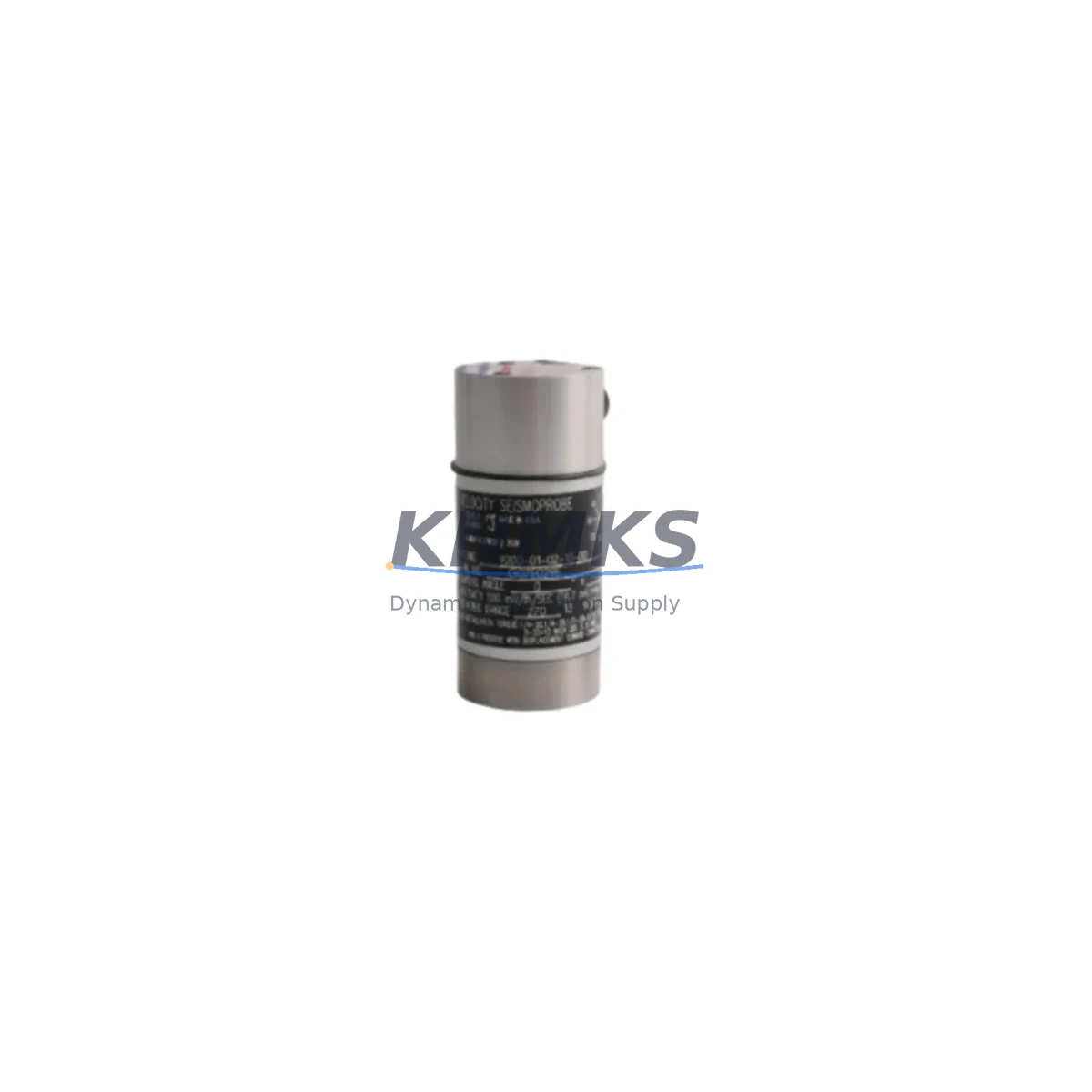
The Bently Nevada 9200-01-02-10-00 is an eddy-current proximity transducer engineered for radial vibration and position measurement in rotating machinery protection systems. As original Bently Nevada 9200 Series units reach end-of-life and OEM supply chains become increasingly constrained, plant engineers and reliability teams are actively sourcing verified drop-in replacements that maintain signal integrity, dimensional compatibility, and system certification without requiring full platform overhauls.
This unit is a direct migration-ready replacement for the discontinued 9200-01-02-10-00 OEM part. It is designed to interface with Bently Nevada 3500 Series monitoring racks, including the 3500/42M Proximitor I/O Module and the 3500/22M Transient Data Interface, without requiring firmware changes or signal recalibration at the rack level. The transducer outputs a standard -24 VDC bias voltage signal compatible with the existing 3500 Series proximitor driver circuitry, preserving alarm setpoints and trip thresholds already configured in the monitoring system.
For facilities running legacy 7200 Series or early 3300 Series machinery protection systems, the 9200-01-02-10-00 can serve as a transitional component during phased migration to the 3500 platform. Engineers should verify gap voltage settings (typically -10.0 VDC at 50 mil gap for standard 5 mm probes), confirm cable extension lengths against the existing 9200 Series extension cable assemblies, and validate that the proximitor driver — such as the 3500/25 Enhanced Keyphasor Module or the 3500/40M Proximitor I/O — is configured for the correct sensitivity scale factor (200 mV/mil or 7.87 V/mm).
Before installation, technicians should confirm the following migration parameters: terminal block wiring polarity at the I/O module, shield grounding continuity along the coaxial cable run, probe tip clearance to the shaft target area, and the absence of ferromagnetic interference within the probe’s sensing range. The 9200-01-02-10-00 uses a standard 5/16-18 UNC thread mount, consistent with existing probe holder brackets in most turbine, compressor, and pump bearing housings.
When integrating this transducer into a control cabinet upgrade or DCS migration project, it is common to simultaneously address the 3500/15 Power Supply Module to ensure adequate rail voltage under expanded I/O load, and to verify that the System 1 Condition Monitoring Software configuration reflects the updated channel assignments. For multi-channel installations, the 3500/42M supports up to four proximity channels per module, reducing rack space requirements during consolidation from older 7200 Series multi-rack configurations.
Communication protocol migration is a key consideration for facilities transitioning from hardwired relay outputs to Modbus RTU or Ethernet/IP-based condition monitoring. The 3500 Series rack supports the 3500/92 Communication Gateway Module, which bridges legacy relay logic to modern SCADA and DCS platforms without disrupting the transducer signal chain. This allows the 9200-01-02-10-00 to remain in service during the communication layer upgrade, minimizing the scope of simultaneous changes and reducing commissioning risk.
All units are pre-shipment tested for bias voltage output, frequency response linearity, and insulation resistance. Each 9200-01-02-10-00 ships with a support terms confirmed by quotation covering manufacturing defects and signal performance. In-stock inventory supports immediate dispatch for emergency replacement and planned maintenance windows alike.
Migration Compatibility Table
| Parameter | 9200-01-02-10-00 (This Unit) | Legacy / OEM Reference |
|---|---|---|
| Thread Mount | 5/16-18 UNC | 5/16-18 UNC (standard 9200 Series) |
| Probe Tip Diameter | 5 mm | 5 mm |
| Sensitivity | 200 mV/mil (7.87 V/mm) | 200 mV/mil |
| Bias Voltage Output | -10.0 VDC @ 50 mil gap | -10.0 VDC @ 50 mil gap |
| Supply Voltage | -24 VDC | -24 VDC |
| Compatible Rack | 3500 Series, 7200 Series (with driver check) | 9200 / 3300 / 7200 Series |
| Compatible I/O Module | 3500/42M Proximitor I/O | 7200/20-xx-xx Proximitor |
| Communication | Analog signal; compatible with 3500/92 Gateway | Hardwired relay / analog |
| Installation Space | Standard probe holder bracket (no modification) | Same bracket footprint |
| Firmware Requirement | No firmware change required at rack level | N/A |
| Commissioning Note | Verify gap voltage and shield grounding on-site | Standard gap-setting procedure |
| Support terms | support terms confirmed by quotation | OEM support terms expired / discontinued |
Retrofit Planning for Existing Automation Systems
A successful retrofit using the 9200-01-02-10-00 typically begins with a rack audit. Technicians should document the current slot assignments within the 3500 Series rack, noting which channels are occupied by the 3500/42M Proximitor I/O Module and whether any slots are shared with the 3500/22M Transient Data Interface for startup and coast-down data capture. If the existing installation uses a 7200 Series proximitor driver, a driver compatibility check is mandatory before swapping the transducer, as the 7200/20-xx-xx Proximitor has different input impedance characteristics than the 3500/42M.
Power budget verification is a critical pre-retrofit step. The 3500/15 Power Supply Module must be confirmed to supply adequate -24 VDC rail current for all active proximity channels, especially when adding channels during an I/O expansion. Overloading the power supply rail is a common cause of intermittent bias voltage drift, which can trigger false alarms or mask genuine vibration events.
For facilities integrating the 9200-01-02-10-00 into a broader control cabinet upgrade — for example, migrating from a standalone machinery protection rack to a unified DCS cabinet with integrated safety logic — the transducer signal should be routed through a signal isolator to prevent ground loop interference between the -24 VDC proximitor circuit and the DCS analog input card. The 3500/92 Communication Gateway Module can then aggregate proximity data alongside temperature and speed channels for transmission to the plant SCADA via Modbus RTU or Ethernet/IP.
Extension cable assemblies must be matched to the probe model. The 9200-01-02-10-00 is compatible with standard 9200 Series coaxial extension cables in 1-meter increments. Total cable length (probe + extension) must remain within the proximitor driver’s specified range to maintain sensitivity accuracy. Technicians should also verify that the Keyphasor signal — typically sourced from a 3500/25 Enhanced Keyphasor Module — is correctly phased relative to the proximity probe angular position for accurate 1X and 2X vibration vector analysis.
Downtime Control During System Migration
Minimizing unplanned downtime during a proximity transducer replacement requires a structured hot-swap protocol. Where process conditions permit, the replacement should be staged during a scheduled maintenance window with the machine at rest. The original program logic in the 3500 Series rack — including alarm setpoints, trip multipliers, and time delays — should be exported and archived using System 1 software before any hardware changes are made. This ensures that if a configuration error occurs during commissioning, the original parameter set can be restored without re-engineering.
For continuous-process facilities where a full shutdown is not feasible, a bypass relay can be temporarily inserted at the 3500/42M I/O terminal block to hold the channel in a non-trip state while the probe is physically replaced. This approach preserves control continuity on adjacent channels and prevents nuisance trips from the open-circuit condition during probe removal. Once the 9200-01-02-10-00 is installed and gap voltage is confirmed within specification, the bypass relay is removed and the channel is returned to normal monitoring mode.
HMI screen updates should be coordinated with the transducer replacement if channel tag names or engineering unit scaling have changed. For facilities using Wonderware, FactoryTalk, or Ignition SCADA platforms, the OPC tag mapping to the 3500/92 Communication Gateway should be verified post-commissioning to confirm that vibration trend data is populating correctly. A 30-minute run-at-speed verification period is recommended before returning the machine to full load, during which vibration amplitude and phase angle should be compared against the historical baseline stored in System 1.
Retrofit Support FAQ
Q: Is the 9200-01-02-10-00 a direct drop-in replacement for the original Bently Nevada OEM part?
A: Yes. This unit replicates the mechanical dimensions, thread specification, sensitivity, and bias voltage output of the original 9200-01-02-10-00. No modifications to the probe holder bracket, extension cable, or proximitor driver are required in standard 9200 Series and 3500 Series installations. Gap voltage should be verified on-site after installation.
Q: What commissioning steps are required after installation?
A: Set the probe gap to achieve a bias voltage of -10.0 VDC (±0.5 VDC) at the proximitor output. Verify shield grounding continuity from the probe tip to the rack terminal block. Confirm that the 3500/42M channel is configured for 200 mV/mil sensitivity. Run a static calibration check using a gap-setting tool before returning the machine to service.
Q: Can this transducer be used with a 7200 Series proximitor driver?
A: Compatibility depends on the specific 7200 Series driver model. The 7200/20-xx-xx Proximitor accepts the same -24 VDC supply and coaxial cable interface, but input impedance and sensitivity scaling should be verified against the driver datasheet. Contact our technical team with your driver model number for a confirmed compatibility assessment.
Q: What are the support terms and supply terms?
A: Each unit carries a support terms confirmed by quotation covering manufacturing defects and signal performance deviations from specification. In-stock units are available for immediate dispatch. For long-term spare parts agreements (12–36 months of forward inventory), contact our sales team to discuss consignment or blanket order arrangements.
© 2026 KNMKS. All rights reserved.
Original Source: https://knmks.com
Contact: admin@knmks.com | +86 18359268345
Product Identification
- Brand / Ecosystem
-
Bently Nevada
Bently Nevada - Model / Series
- 9200-01-02-10-00
- Product Family
- Sensors
- Availability Status
- Available on request after model and quantity confirmation
- Inquiry Type
- B2B RFQ, replacement inquiry and project spare-part request
- Pre-Quote Check
- Exact SKU, brand, series, quantity, nameplate photos and destination country are checked before quotation
System Path
Where this product fits in the KNMKS automation structure.
Specification & Inquiry Focus
- Sensor range
- Photoelectric, proximity and process sensors
- Common needs
- Output type, distance and connector
- Project support
- Machine detection and replacement inquiry
Buyer Confirmation
Information KNMKS checks before replying.
- Exact model
- 9200-01-02-10-00
- Brand / ecosystem
- Bently Nevada
- Product family
- Sensors
- Application note
- Replacement, maintenance, project build or spare-part list
- Useful photos
- Nameplate, installed unit, cabinet layout or connector side
- Delivery details
- Quantity, destination country and target schedule
Document Support
Files and notes can be confirmed during quotation.
- Product photos or nameplate confirmation when available
- Packing and delivery notes before quotation confirmation
- Support scope and delivery terms confirmed per inquiry
- Export document coordination for qualified B2B requests
Inquiry Support
- NPN/PNP, analog and digital output checking
- Connector and cable compatibility review
- Fast inquiry support for maintenance teams
What to Send Us
- Brand and exact model number: Bently Nevada 9200-01-02-10-00
- Quantity and required delivery time
- Application, replacement requirement or nameplate photo
- Destination country and shipping preference
RFQ Preparation
This is a product inquiry page built for RFQ communication.
Fast Model Check
Send this model to KNMKS for confirmation.
Include quantity, destination country and photos if this is a maintenance replacement. The inquiry will be saved with a reference number after submission.
Brand & Compatibility Note
KNMKS displays automation product information for well-known industrial brand ecosystems and compatible replacement references. Brand names are used for product identification and compatibility reference only; final availability and commercial terms are confirmed per quotation.
 Manufacturing
 Machine Tools
 Packaging
 Energy & Power

 PLCs & Controllers
 HMI & Displays
 Servo Systems
 Variable Frequency Drives