
Overview
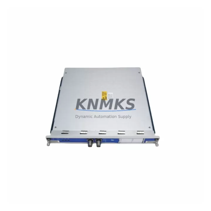
Bently Nevada 3500/50M 286566-02 Migration-Ready Tachometer for Legacy Control Systems
The Bently Nevada 3500/50M 286566-02 (alternate part number 288062-02) is a migration-ready tachometer module engineered for direct integration into existing Bently Nevada 3500 Series machinery protection racks. As legacy vibration monitoring infrastructure reaches end-of-life, this module serves as the primary retrofit solution for facilities seeking to extend operational continuity without full system replacement. Whether your plant is transitioning from an older 3300 Series platform or consolidating multiple monitoring channels into a modernized 3500 rack, the 3500/50M 286566-02 provides a verified, drop-in upgrade path with minimal engineering overhead.
Before initiating any retrofit or replacement procedure, engineers must confirm several critical parameters. Power supply capacity within the existing rack must be validated — the 3500 Series backplane distributes both +24 VDC and ±15 VDC rails, and adding or replacing a tachometer module requires verifying that the 3500/20 Power Supply Module can sustain the additional load without triggering overcurrent protection. Terminal wiring from the field transducer must be mapped against the module’s input specifications, particularly for proximity probe signal conditioning, where gap voltage, sensitivity (mV/mil), and cable length all affect measurement accuracy.
Backplane slot assignment is equally important. The 3500/50M occupies a single slot in the 3500 rack and must be addressed correctly within the System 1 configuration software or the legacy Rack Configuration Software (RCS). Incorrect module addressing will prevent the rack from recognizing the tachometer channel, causing false trip conditions or silent failures. If the existing rack already contains a 3500/53 Overspeed Detection Module or a 3500/40M Proximitor/Seismic Monitor, slot sequencing must be reviewed to avoid address conflicts on the shared backplane communication bus.
Program compatibility is a frequent concern during tachometer module migration. Facilities running older firmware on the 3500 rack controller may need to update to a compatible firmware revision before the 3500/50M 286566-02 is recognized. Bently Nevada’s firmware versioning is rack-wide, meaning a firmware update affects all installed modules simultaneously — a factor that requires coordinated downtime planning and pre-update backup of all rack configuration files. HMI screens configured in System 1 Evolution or third-party SCADA platforms must also be reviewed to ensure tachometer channel tags, engineering unit scaling, and alarm setpoints are correctly mapped to the new module’s output format.
Communication link integrity between the 3500 rack and the plant DCS or safety system must be verified post-installation. The 3500 Series supports Modbus RTU, Modbus TCP/IP, and OPC DA/UA protocols depending on the installed 3500/92 Communication Gateway Module. During migration, engineers should confirm that the gateway’s register map still correctly references the tachometer channel after the module swap, and that no polling timeouts have been introduced by the configuration change. Where the plant uses a 3500/22M Transient Data Interface for waveform capture, the tachometer keyphasor signal routing must also be re-validated to ensure phase reference data is correctly acquired for orbit and spectrum analysis.
Migration Compatibility Table
| Parameter | 3500/50M 286566-02 | Notes / Retrofit Guidance |
|---|---|---|
| Part Number | 286566-02 / 288062-02 | Both numbers reference the same module revision |
| Rack Compatibility | Bently Nevada 3500 Series | Single-slot installation; verify slot addressing in RCS |
| Input Signal Type | Proximity Probe / Magnetic Pickup | Confirm transducer type and cable impedance before wiring |
| Power Requirement | Supplied via 3500 backplane | Validate 3500/20 PSU capacity before installation |
| Communication Protocol | Modbus RTU / TCP, OPC via 3500/92 | Verify gateway register map post-swap |
| Firmware Compatibility | Rack-wide firmware dependency | Backup rack config before any firmware update |
| Installation Space | Single rack slot (standard 3500 form factor) | No additional panel space required |
| Replacement Path | Direct replacement for legacy tachometer channels | Suitable for 3300 Series migration to 3500 platform |
| Commissioning | RCS / System 1 configuration required | Full channel calibration and trip test recommended |
| Support terms | support terms confirmed by quotation | Covers manufacturing defects; includes pre-shipment functional test |
Retrofit Planning for Existing Automation Systems
Successful integration of the 3500/50M 286566-02 into a legacy automation environment requires a structured retrofit plan that accounts for both hardware and software interdependencies. The module’s installation begins at the rack level: the 3500 Series backplane must be inspected for corrosion, damaged connector pins, and proper grounding continuity before the new module is seated. If the rack is being upgraded from a partial 3300 Series installation, the 3500/01 Rack Interface Module must be present and correctly configured to manage inter-module communication.
Field wiring from proximity probes or magnetic pickups must be terminated at the module’s front-panel terminal block. Engineers should verify that the existing cable shielding is grounded at one end only — typically at the rack end — to prevent ground loop interference that can corrupt tachometer readings. Where cable runs exceed recommended lengths, signal conditioning through a dedicated barrier or isolator may be required to maintain signal integrity.
On the software side, the 3500/50M 286566-02 must be configured within the Rack Configuration Software to define keyphasor assignment, speed range, and trip multiplier settings. If the plant operates a System 1 Evolution platform, the module’s channel configuration must be synchronized with the historian tags and alarm management database. Facilities using a 3500/22M Transient Data Interface for startup and coast-down analysis will need to re-map the keyphasor input to ensure that waveform capture is correctly triggered by the new tachometer channel.
Where the retrofit involves expanding I/O capacity, the 3500/50M can coexist with other modules in the same rack, including the 3500/40M Proximitor/Seismic Monitor for radial vibration, the 3500/42M Proximitor/Seismic Monitor for axial position, and the 3500/45 Position Monitor for thrust measurement. Coordinating the slot assignments of these modules during a multi-channel retrofit minimizes the risk of address conflicts and simplifies the final system verification process.
Downtime Control During System Migration
Minimizing unplanned downtime is the primary operational concern during any tachometer module replacement. A structured migration approach begins with a complete backup of the existing rack configuration file using the Rack Configuration Software, followed by documentation of all current alarm setpoints, trip levels, and channel scaling factors. This baseline record ensures that the replacement module can be configured to match the original system behavior exactly, reducing the risk of nuisance trips or missed alarms during the commissioning phase.
Where process conditions permit, the module swap should be performed during a scheduled maintenance window with the machinery at rest. If hot-swap capability is required, the 3500 rack’s bypass and inhibit functions should be activated for the affected channel before the module is removed, preventing false trip signals from propagating to the plant safety system or DCS. After the new 3500/50M 286566-02 is seated and the rack configuration is loaded, a full channel functional test — including gap voltage verification, speed simulation, and trip relay actuation — should be completed before the bypass is released.
For facilities where continuous operation is critical, a parallel monitoring strategy can be employed: a temporary portable vibration analyzer is connected to the transducer output to maintain speed monitoring coverage while the rack module is being replaced. This approach is particularly effective in power generation and petrochemical applications where machinery protection cannot be interrupted. Once the new module passes all functional tests and the System 1 or SCADA displays confirm correct channel data, the portable analyzer is disconnected and the permanent monitoring system is returned to service.
Pre-shipment functional testing of the 3500/50M 286566-02 is performed before dispatch to verify that the module meets Bently Nevada’s original performance specifications. Each unit is tested for input sensitivity, frequency response, trip relay operation, and communication output integrity. A support terms confirmed by quotation cover all manufacturing defects identified after installation, providing assurance that the replacement module will perform reliably throughout the initial post-retrofit operating period.
Retrofit Support FAQ
Q: Is the 3500/50M 286566-02 a direct replacement for the 288062-02?
A: Yes. The part numbers 286566-02 and 288062-02 reference the same module revision and are interchangeable within the 3500 Series rack. Both designations are accepted when ordering, and the module’s firmware and hardware configuration are identical regardless of which part number appears on the label.
Q: What wiring changes are required when replacing a legacy tachometer module?
A: In most cases, existing field wiring can be reused without modification. Engineers should verify terminal block pin assignments against the 3500/50M installation drawing, confirm cable shielding continuity, and check that the transducer gap voltage falls within the module’s specified input range. If the legacy module used a different connector format, a wiring adapter or re-termination at the front panel may be required.
Q: How is the module commissioned after installation?
A: After seating the module and loading the rack configuration file, the channel must be calibrated using the Rack Configuration Software. This includes setting the keyphasor assignment, defining the speed range and full-scale output, and configuring the trip and alert setpoints. A functional test using a speed simulator or by rotating the monitored machine at a known speed is recommended to verify that the module’s output matches the expected engineering units before the bypass is released.
Q: What does the support terms confirmed by quotation cover, and is pre-shipment testing included?
A: The support terms confirmed by quotation cover manufacturing defects in materials and workmanship identified after installation under normal operating conditions. Every unit undergoes pre-shipment functional testing to verify input sensitivity, trip relay operation, and communication output before dispatch. In-stock units are available for immediate shipment, supporting urgent replacement requirements where extended lead times are not acceptable.
© 2026 KNMKS. All rights reserved.
Original Source: https://knmks.com
Contact: admin@knmks.com | +86 18359268345
Product Identification
- Brand / Ecosystem
-
Bently Nevada
Bently Nevada - Model / Series
-
3500/50M 286566-02 288062-02
3500 Series - Product Family
- Other Components
- Availability Status
- Available on request after model and quantity confirmation
- Inquiry Type
- B2B RFQ, replacement inquiry and project spare-part request
- Pre-Quote Check
- Exact SKU, brand, series, quantity, nameplate photos and destination country are checked before quotation
System Path
Where this product fits in the KNMKS automation structure.
Specification & Inquiry Focus
- Component range
- Breakers, terminals and cabinet accessories
- Common needs
- Model, photo and installation requirement
- Project support
- Maintenance and mixed spare-part inquiry
Buyer Confirmation
Information KNMKS checks before replying.
- Exact model
- 3500/50M 286566-02 288062-02
- Brand / ecosystem
- Bently Nevada
- Product family
- Other Components
- Application note
- Replacement, maintenance, project build or spare-part list
- Useful photos
- Nameplate, installed unit, cabinet layout or connector side
- Delivery details
- Quantity, destination country and target schedule
Document Support
Files and notes can be confirmed during quotation.
- Product photos or nameplate confirmation when available
- Packing and delivery notes before quotation confirmation
- Support scope and delivery terms confirmed per inquiry
- Export document coordination for qualified B2B requests
Inquiry Support
- Mixed automation spare parts inquiry
- Cabinet component and accessory support
- Model identification from photos or labels
What to Send Us
- Brand and exact model number: Bently Nevada 3500/50M 286566-02 288062-02
- Quantity and required delivery time
- Application, replacement requirement or nameplate photo
- Destination country and shipping preference
RFQ Preparation
This is a product inquiry page built for RFQ communication.
Fast Model Check
Send this model to KNMKS for confirmation.
Include quantity, destination country and photos if this is a maintenance replacement. The inquiry will be saved with a reference number after submission.
Brand & Compatibility Note
KNMKS displays automation product information for well-known industrial brand ecosystems and compatible replacement references. Brand names are used for product identification and compatibility reference only; final availability and commercial terms are confirmed per quotation.
 Manufacturing
 Machine Tools
 Packaging
 Energy & Power
 PLCs & Controllers
 HMI & Displays
 Servo Systems
 Variable Frequency Drives