
Overview
Bently Nevada 3500/44M 176449-99 Migration-Ready Overspeed Monitor for Legacy Control Systems
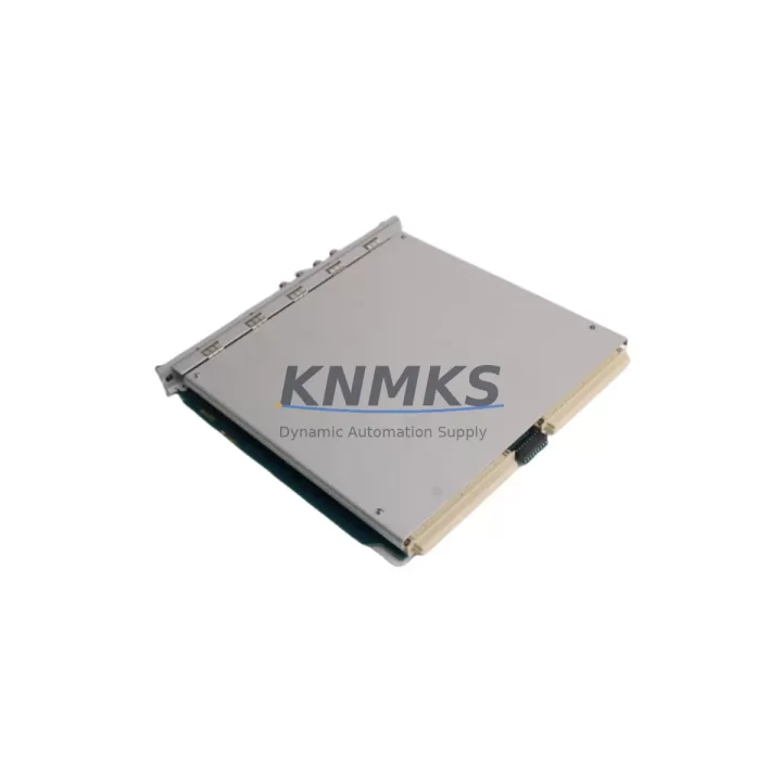
The Bently Nevada 3500/44M 176449-99 is a high-reliability overspeed detection module engineered for continuous operation in rotating machinery protection systems. As legacy 3500 Series installations approach end-of-support milestones, this migration-ready replacement module provides a direct, back-to-back compatible upgrade path for turbine control panels, compressor trains, and critical rotating equipment monitored under API 670 standards. Whether you are replacing a failed unit, building a spare-parts buffer, or executing a planned control system modernization, the 3500/44M 176449-99 delivers the signal integrity, rack compatibility, and firmware alignment required for zero-compromise retrofits.
The module slots directly into the 3500 Series rack backplane without mechanical modification. Terminal wiring follows the standard 3500 I/O module pinout, meaning existing field cables, junction boxes, and marshalling panels remain undisturbed during swap-out. Before installation, engineers should verify the rack power supply — typically the 3500/15 Power Supply module — is rated to support the additional current draw if adjacent slots are being populated simultaneously. Confirm the system’s overall power budget across all installed modules before energizing the upgraded rack.
Backplane slot addressing must be confirmed against the existing rack configuration file. The 3500/44M 176449-99 supports both standard and enhanced overspeed detection modes; the active mode is set via the System 1 configuration software or the rack’s local configuration interface. If the legacy installation used an earlier firmware revision, a firmware compatibility check against the current rack controller — often the 3500/22M Transient Data Interface or the 3500/20 Rack Interface Module — is recommended before final commissioning. Mismatched firmware versions between the monitor module and the rack interface can cause false trip events or communication dropouts on the Modbus RTU or Ethernet/IP link used by the plant DCS.
For plants running Emerson Ovation DCS or Honeywell Experion PKS as the supervisory layer, the 3500 rack communicates via a dedicated serial or Ethernet gateway. Verify that the gateway configuration — baud rate, node address, and polling interval — matches the replacement module’s communication parameters. If the plant uses a 3500/92 Communication Gateway, confirm that the gateway firmware supports the 3500/44M 176449-99 module descriptor before going live. Communication link validation should be completed during a scheduled maintenance window to avoid spurious alarms reaching the DCS historian.
HMI faceplate updates are often overlooked during module replacements. If the control room HMI — whether a Wonderware InTouch station or a Yokogawa CENTUM VP operator console — displays overspeed trip status from the 3500 rack, verify that the tag mapping and alarm setpoint values are correctly transferred to the replacement module’s configuration. Overspeed trip setpoints, danger levels, and alert thresholds stored in the legacy module’s non-volatile memory are not automatically migrated; they must be re-entered and verified against the original engineering documentation or the last approved loop calibration record.
Installation space confirmation is straightforward: the 3500/44M 176449-99 occupies a single slot in the standard 3500 Series 19-inch rack. No additional mounting hardware or DIN rail adapters are required. If the control cabinet has limited depth clearance, verify that the module’s rear connector and any attached I/O terminal block do not conflict with cable trays or adjacent equipment. Adequate ventilation clearance around the rack should be maintained per Bently Nevada installation guidelines to ensure thermal performance within specification.
Migration Compatibility Table
| Parameter | Details |
|---|---|
| SKU / Part Number | 3500/44M 176449-99 |
| Brand / Series | Bently Nevada / 3500 Series |
| Module Function | Overspeed Detection Monitor |
| Rack Compatibility | 3500 Series 19-inch Rack (standard backplane) |
| Slot Requirement | Single slot, standard 3500 I/O slot |
| Terminal Wiring | Compatible with existing 3500 Series I/O terminal pinout |
| Communication Protocols | Modbus RTU, Ethernet/IP (via 3500/92 gateway) |
| Firmware Compatibility | Verify against 3500/22M or 3500/20 rack interface firmware revision |
| Configuration Software | Bently Nevada System 1 / Rack Configuration Utility |
| Power Supply Requirement | Confirm rack power budget via 3500/15 Power Supply module |
| Legacy Replacement Target | Earlier 3500/44 and 3500/44M variants (confirm part suffix compatibility) |
| Commissioning Requirement | Setpoint re-entry, firmware check, DCS communication validation |
| Support terms | support terms confirmed by quotation — covers manufacturing defects and functional failure |
| Shipping | Global stock available; expedited dispatch supported |
Retrofit Planning for Existing Automation Systems
A successful retrofit of the 3500/44M 176449-99 into an existing protection system begins with a thorough pre-outage audit. The engineering team should collect the current rack configuration file, the as-built wiring diagrams for the overspeed detection loop, and the DCS tag list associated with the 3500 rack’s Modbus or Ethernet/IP node. This documentation forms the baseline against which the replacement module’s configuration will be validated.
During the audit, inspect the condition of the existing I/O terminal blocks and field wiring. If the terminal blocks show signs of corrosion or insulation degradation, plan to replace them concurrently with the module swap to avoid introducing new fault points into the protection loop. The 3500 Series uses a removable terminal block design, which simplifies this process without requiring full field cable re-termination.
Adjacent modules in the rack — such as the 3500/40M Proximitor/Seismic Monitor, the 3500/50M Tachometer module, or the 3500/32 4-Channel Relay module — should be inspected for firmware currency and physical condition as part of the same maintenance window. Replacing the overspeed monitor while leaving adjacent modules on outdated firmware creates a mixed-revision environment that can complicate future troubleshooting. If the rack also includes a 3500/60 Temperature Monitor or a 3500/70M High-Speed Relay module, verify that their configuration files are backed up before any rack power cycling.
Signal isolators installed between the speed sensor outputs and the 3500/44M input terminals should be tested for calibration accuracy before the new module is commissioned. A miscalibrated signal isolator will produce incorrect speed readings regardless of the monitor module’s internal accuracy. If the plant uses Pepperl+Fuchs or MTL signal conditioning barriers in the overspeed detection loop, confirm their output range matches the 3500/44M 176449-99 input specification.
Programming cable and laptop connectivity for the System 1 configuration utility should be tested on a bench unit or a spare rack before the maintenance window begins. Confirm that the USB-to-serial adapter or Ethernet connection to the rack interface module is recognized by the configuration software. A failed configuration connection during a live maintenance window is a common source of unplanned downtime extension.
Downtime Control During System Migration
Minimizing downtime during a 3500/44M 176449-99 replacement requires a structured pre-outage preparation protocol. The most effective approach is to pre-configure the replacement module on a bench rack or in the System 1 offline configuration environment before the maintenance window opens. Load the overspeed trip setpoints, alert thresholds, and communication parameters into the module’s configuration file, verify them against the approved engineering documentation, and save a signed-off configuration backup. When the maintenance window opens, the physical swap and configuration download can be completed in under 30 minutes for a well-prepared team.
To protect the original program logic and DCS integration, export the full rack configuration file from the existing installation before removing the legacy module. Store this file in a version-controlled document management system alongside the as-built wiring diagrams. If the replacement module requires a firmware update to match the rack interface revision, perform the update on the bench before installation to avoid firmware update delays during the live outage window.
During the physical swap, follow a controlled de-energization sequence: isolate the rack from the DCS communication link first, then remove the module from the powered rack using the standard 3500 Series hot-swap procedure if supported by the rack revision. Confirm with the plant safety team whether the overspeed protection loop must be bypassed at the turbine control system level before the module is removed. Bypassing the protection loop without proper authorization and documentation is a safety and compliance risk.
After installation, perform a staged recommissioning: restore the DCS communication link, verify that the module appears correctly on the System 1 network, confirm that all configured channels are reading correctly, and perform a simulated overspeed trip test before returning the unit to service. Document the as-left configuration and the test results in the plant’s maintenance management system. This record supports future audits and reduces the risk of repeat failures being misattributed to the replacement module.
Retrofit Support FAQ
Q1: Is the 3500/44M 176449-99 a direct drop-in replacement for earlier 3500/44M variants?
In most cases, yes — the 3500/44M 176449-99 is designed for backplane and terminal compatibility with earlier 3500/44M revisions. However, the part number suffix (-99) may indicate a specific hardware or firmware revision. Always cross-reference the legacy module’s part number against Bently Nevada’s compatibility matrix and confirm with your engineering team before installation in a live protection system.
Q2: What commissioning steps are required after installing the replacement module?
Required commissioning steps include: downloading the pre-configured configuration file via System 1, verifying all channel setpoints against the approved loop calibration records, confirming DCS communication link integrity (Modbus RTU or Ethernet/IP), performing a simulated overspeed trip test, and documenting the as-left configuration. If the rack firmware was updated as part of the replacement, a full rack communication test is also required.
Q3: How is the 3500/44M 176449-99 tested before shipment?
Each unit undergoes functional testing prior to dispatch, including power-on self-test verification, communication interface check, and channel output validation. Units are shipped with a test report confirming functional status. The support terms confirmed by quotation cover manufacturing defects and functional failure under normal operating conditions from the date of shipment.
Q4: What is the typical lead time and stock availability?
The 3500/44M 176449-99 is maintained in global stock to support emergency replacement and planned maintenance programs. Standard dispatch is available for in-stock units, with expedited shipping options for critical plant shutdowns. Contact our sales team for current stock levels and lead time confirmation for your region.
© 2026 KNMKS. All rights reserved.
Original Source: https://knmks.com
Contact: admin@knmks.com | +86 18359268345
Product Identification
- Brand / Ecosystem
-
Bently Nevada
Bently Nevada - Model / Series
-
3500/44M 176449-99
3500 Series - Product Family
- Other Components
- Availability Status
- Available on request after model and quantity confirmation
- Inquiry Type
- B2B RFQ, replacement inquiry and project spare-part request
- Pre-Quote Check
- Exact SKU, brand, series, quantity, nameplate photos and destination country are checked before quotation
System Path
Where this product fits in the KNMKS automation structure.
Specification & Inquiry Focus
- Component range
- Breakers, terminals and cabinet accessories
- Common needs
- Model, photo and installation requirement
- Project support
- Maintenance and mixed spare-part inquiry
Buyer Confirmation
Information KNMKS checks before replying.
- Exact model
- 3500/44M 176449-99
- Brand / ecosystem
- Bently Nevada
- Product family
- Other Components
- Application note
- Replacement, maintenance, project build or spare-part list
- Useful photos
- Nameplate, installed unit, cabinet layout or connector side
- Delivery details
- Quantity, destination country and target schedule
Document Support
Files and notes can be confirmed during quotation.
- Product photos or nameplate confirmation when available
- Packing and delivery notes before quotation confirmation
- Support scope and delivery terms confirmed per inquiry
- Export document coordination for qualified B2B requests
Inquiry Support
- Mixed automation spare parts inquiry
- Cabinet component and accessory support
- Model identification from photos or labels
What to Send Us
- Brand and exact model number: Bently Nevada 3500/44M 176449-99
- Quantity and required delivery time
- Application, replacement requirement or nameplate photo
- Destination country and shipping preference
RFQ Preparation
This is a product inquiry page built for RFQ communication.
Fast Model Check
Send this model to KNMKS for confirmation.
Include quantity, destination country and photos if this is a maintenance replacement. The inquiry will be saved with a reference number after submission.
Brand & Compatibility Note
KNMKS displays automation product information for well-known industrial brand ecosystems and compatible replacement references. Brand names are used for product identification and compatibility reference only; final availability and commercial terms are confirmed per quotation.
 Manufacturing
 Machine Tools
 Packaging
 Energy & Power
 PLCs & Controllers
 HMI & Displays
 Servo Systems
 Variable Frequency Drives