
Overview
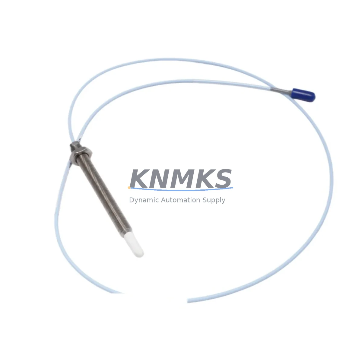
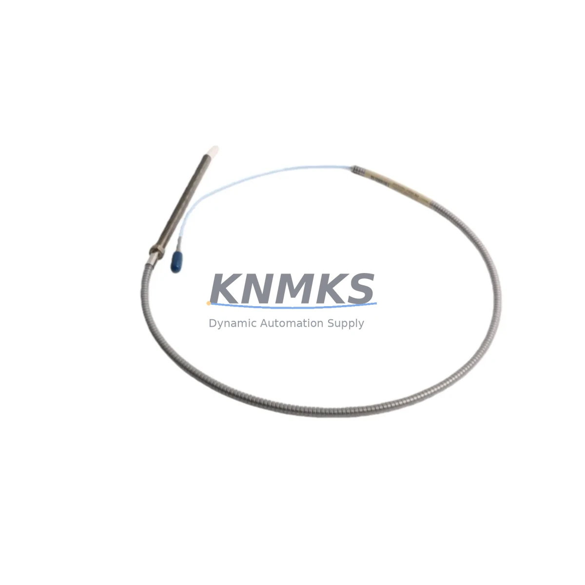
Bently Nevada 330905-00-12-05-02-RU Migration-Ready Proximity Probe for Legacy Control Systems
The Bently Nevada 330905-00-12-05-02-RU is an eddy current proximity probe engineered for seamless integration into aging vibration monitoring architectures. As industrial facilities accelerate the retirement of first- and second-generation 3300 Series monitoring systems, this probe serves as a validated, drop-in replacement that preserves existing wiring infrastructure, terminal block assignments, and signal conditioning chains. Whether your plant is migrating from a legacy 3300 XL NSv monitor to a modern 3500/42M Proximitor I/O Module, or consolidating scattered proximity channels into a unified rack, the 330905-00-12-05-02-RU delivers the dimensional and electrical compatibility required to complete the transition without reengineering the entire measurement loop.
Facilities that have operated Bently Nevada 3300 XL proximity systems for more than a decade frequently encounter the same set of challenges: discontinued firmware support, unavailable spare driver boards, and calibration certificates that no longer meet ISO 10816 audit requirements. The 330905-00-12-05-02-RU addresses these pain points directly. Its 5 mm tip diameter, 12 mm cable length extension, and standard -5 VDC to -24 VDC output range are fully compatible with the Bently Nevada 3300 XL Driver and the 3500/42 Proximitor Monitor, allowing engineers to swap the probe at the field end without modifying the junction box wiring or reconfiguring the monitor’s gap voltage setpoints.
During retrofit planning, engineers must verify several critical parameters before committing to a probe replacement. Power supply capacity at the local marshalling cabinet must support the probe’s quiescent current draw alongside any co-located 3500/20 Power Supply modules already serving the rack. Terminal block torque specifications on the existing field wiring—typically Bently Nevada standard 2-wire shielded cable—must be confirmed against the replacement probe’s connector pinout to avoid intermittent signal faults after commissioning. Backplane slot assignments within the 3500 Rack must be audited to confirm that the Proximitor I/O module address matches the channel mapping stored in the System 1 Evolution software database, preventing false alarm conditions during the first live run after cutover.
Program compatibility is equally important. If the plant’s DCS or safety instrumented system reads vibration data via Modbus RTU or FOUNDATION Fieldbus from a 3500/22M Transient Data Interface, the engineering team must confirm that the new probe’s sensitivity factor (typically 7.87 V/mm for standard gap range) is correctly entered into the monitor’s configuration before the loop is closed. HMI faceplate graphics that display gap voltage, direct vibration amplitude, and 1X/2X vector components must be updated to reflect the new probe’s calibration curve, particularly if the legacy system used a non-standard sensitivity coefficient inherited from an earlier 3300 XL calibration run.
Migration Compatibility Table
| Parameter | Legacy System (3300 XL NSv) | 330905-00-12-05-02-RU (Replacement) | Notes |
|---|---|---|---|
| Probe Tip Diameter | 5 mm | 5 mm | Direct dimensional match; no target modification required |
| Cable Length | Standard extension options | 12 mm extension | Confirm total cable length against driver input specification |
| Output Voltage Range | -5 VDC to -24 VDC | -5 VDC to -24 VDC | Compatible with 3300 XL Driver and 3500/42 Proximitor |
| Sensitivity | 7.87 V/mm (200 mV/mil) | 7.87 V/mm (200 mV/mil) | Re-enter in monitor configuration after swap |
| Supply Voltage | -24 VDC (from driver) | -24 VDC (from driver) | Verify 3500/20 Power Supply capacity before installation |
| Connector Type | Standard BN coaxial | Standard BN coaxial | No adapter required for existing field cable |
| Communication Protocol | Analog / Modbus RTU | Analog / Modbus RTU | Compatible with 3500/22M Transient Data Interface |
| Rack Compatibility | 3500 Rack (3500/05 Rack) | 3500 Rack (3500/05 Rack) | Confirm slot address in System 1 Evolution database |
| Installation Space | Standard probe boss / bracket | Standard probe boss / bracket | Verify radial clearance at bearing housing |
| Firmware Dependency | 3300 XL firmware (EOL) | None (passive probe) | Monitor firmware update may be required on 3500/42M |
| Support terms | N/A (legacy, discontinued) | support terms confirmed by quotation | Covered from date of shipment; includes functional test certificate |
Retrofit Planning for Existing Automation Systems
A successful retrofit begins well before the maintenance window opens. The engineering team should pull the existing loop drawings and cross-reference the probe’s installation position—radial or axial—against the 3500/42 Proximitor I/O Module’s channel configuration. If the plant is simultaneously upgrading the monitoring rack from a 3500/05 Rack to a newer chassis, the 3500/20 Power Supply module must be sized to handle the combined current demand of all installed Proximitor channels, including any 3500/40M Proximitor I/O Modules serving thrust position measurements on the same shaft train.
Wiring continuity from the probe tip through the extension cable to the driver input must be verified with a calibrated ohmmeter before the system is energized. The 3300 XL Driver, if retained during a partial upgrade, must have its gap voltage setpoints confirmed against the new probe’s linear range. In cases where the driver is also being replaced as part of a full channel upgrade, the 3500/42M Proximitor I/O Module should be pre-configured on the bench using the 3500 Rack Configuration Software before installation, reducing live commissioning time at the machine.
For plants integrating the new probe into a System 1 Evolution condition monitoring platform, the probe’s sensitivity and gap voltage data must be entered into the measurement point database before the first data acquisition scan. If the control room uses a Rockwell Automation ControlLogix PLC to aggregate vibration alarms via the 3500/92 Communication Gateway Module, the gateway’s tag mapping table must be updated to reflect any channel address changes introduced during the rack reconfiguration. Signal isolators installed between the monitor output and the PLC analog input card should also be inspected for range compatibility, as some legacy isolators were calibrated for the narrower output swing of older 3300 Series monitors.
Where I/O expansion is part of the upgrade scope, adding a 3500/64 Dynamic Pressure Monitor or a 3500/50M Tachometer I/O Module to the same rack requires a fresh power budget calculation. The 330905-00-12-05-02-RU’s low quiescent current draw makes it well-suited for dense rack configurations where power headroom is limited. Programming cables used during bench configuration—such as the Bently Nevada RS-232 to USB adapter for legacy rack interfaces—should be tested before the maintenance window to avoid delays caused by driver compatibility issues on modern engineering workstations.
Downtime Control During System Migration
Minimizing unplanned downtime during a proximity probe replacement requires a structured pre-outage checklist and a clearly defined rollback procedure. Before the machine is taken offline, the existing gap voltage reading should be recorded from the 3500/42 Proximitor I/O Module’s front-panel display or from the System 1 Evolution trend screen. This baseline value serves as the acceptance criterion during post-installation verification: after the 330905-00-12-05-02-RU is installed and the gap is set to the manufacturer’s recommended linear midpoint, the new gap voltage should fall within ±0.5 VDC of the recorded baseline, confirming that the probe is seated correctly and the target surface condition has not changed.
The original program logic in the safety instrumented system or DCS should not be modified during the probe swap. All alarm setpoints, trip multipliers, and time delays stored in the 3500/42M monitor should be exported to a configuration backup file before the outage begins, using the 3500 Rack Configuration Software. If the monitor’s firmware requires an update to support the replacement probe’s calibration data format, the firmware upgrade should be performed and validated on a spare module in the workshop before the field unit is touched, eliminating the risk of a failed firmware flash extending the maintenance window.
Field commissioning should follow a defined sequence: energize the power supply, verify gap voltage at the monitor front panel, confirm alarm relay states are de-energized at the correct gap, then release the machine for slow-roll observation before returning to full operating speed. Any deviation from the expected gap voltage trend during slow-roll should be investigated before the machine is loaded, as a misaligned probe or a damaged extension cable connector will produce erratic 1X vector readings that can trigger spurious trips. With the 330905-00-12-05-02-RU’s factory-tested output linearity and the support terms confirmed by quotation covering the full post-installation period, the risk profile of the replacement is significantly lower than continuing to operate with an aging probe of unknown remaining service life.
Retrofit Support FAQ
Q1: Is the 330905-00-12-05-02-RU a direct replacement for the original 330905 series probes used in 3300 XL NSv systems?
Yes. The 330905-00-12-05-02-RU shares the same tip diameter, sensitivity, output voltage range, and connector type as the original 330905 series probes. It is compatible with the 3300 XL Driver and the 3500/42 Proximitor I/O Module without requiring any mechanical or electrical modifications to the existing installation.
Q2: What pre-shipment testing is performed on each unit?
Each 330905-00-12-05-02-RU undergoes a full functional test prior to shipment, including gap voltage linearity verification across the probe’s specified measurement range and output impedance confirmation. A test certificate is included with each unit. Units are shipped in anti-static packaging with physical protection for the probe tip and cable connector.
Q3: How should the gap voltage be set after installation, and does the 3500/42 monitor need to be reconfigured?
After mechanical installation, adjust the probe gap to achieve the monitor’s recommended gap voltage (typically -10 VDC to -12 VDC at the linear midpoint for standard 5 mm probes). The 3500/42 Proximitor I/O Module’s sensitivity factor should be confirmed in the 3500 Rack Configuration Software and set to 7.87 V/mm (200 mV/mil) if not already configured. No other monitor reconfiguration is required for a like-for-like probe replacement.
Q4: What does the support terms confirmed by quotation cover, and what is the process for a support terms claim?
The support terms confirmed by quotation cover manufacturing defects, output linearity failures, and cable integrity issues from the date of shipment. It does not cover damage resulting from incorrect installation, overvoltage conditions, or mechanical impact. To initiate a support terms claim, contact admin@knmks.com with the order number and a description of the observed fault. Replacement units are dispatched within 3 business days of claim approval.
© 2026 KNMKS. All rights reserved.
Original Source: https://knmks.com
Contact: admin@knmks.com | +86 18359268345
Product Identification
- Brand / Ecosystem
-
Bently Nevada
Bently Nevada - Model / Series
-
330905-00-12-05-02-RU
3500 Series - Product Family
- Sensors
- Availability Status
- Available on request after model and quantity confirmation
- Inquiry Type
- B2B RFQ, replacement inquiry and project spare-part request
- Pre-Quote Check
- Exact SKU, brand, series, quantity, nameplate photos and destination country are checked before quotation
System Path
Where this product fits in the KNMKS automation structure.
Specification & Inquiry Focus
- Sensor range
- Photoelectric, proximity and process sensors
- Common needs
- Output type, distance and connector
- Project support
- Machine detection and replacement inquiry
Buyer Confirmation
Information KNMKS checks before replying.
- Exact model
- 330905-00-12-05-02-RU
- Brand / ecosystem
- Bently Nevada
- Product family
- Sensors
- Application note
- Replacement, maintenance, project build or spare-part list
- Useful photos
- Nameplate, installed unit, cabinet layout or connector side
- Delivery details
- Quantity, destination country and target schedule
Document Support
Files and notes can be confirmed during quotation.
- Product photos or nameplate confirmation when available
- Packing and delivery notes before quotation confirmation
- Support scope and delivery terms confirmed per inquiry
- Export document coordination for qualified B2B requests
Inquiry Support
- NPN/PNP, analog and digital output checking
- Connector and cable compatibility review
- Fast inquiry support for maintenance teams
What to Send Us
- Brand and exact model number: Bently Nevada 330905-00-12-05-02-RU
- Quantity and required delivery time
- Application, replacement requirement or nameplate photo
- Destination country and shipping preference
RFQ Preparation
This is a product inquiry page built for RFQ communication.
Fast Model Check
Send this model to KNMKS for confirmation.
Include quantity, destination country and photos if this is a maintenance replacement. The inquiry will be saved with a reference number after submission.
Brand & Compatibility Note
KNMKS displays automation product information for well-known industrial brand ecosystems and compatible replacement references. Brand names are used for product identification and compatibility reference only; final availability and commercial terms are confirmed per quotation.
 Manufacturing
 Machine Tools
 Packaging
 Energy & Power

 PLCs & Controllers
 HMI & Displays
 Servo Systems
 Variable Frequency Drives