
Overview
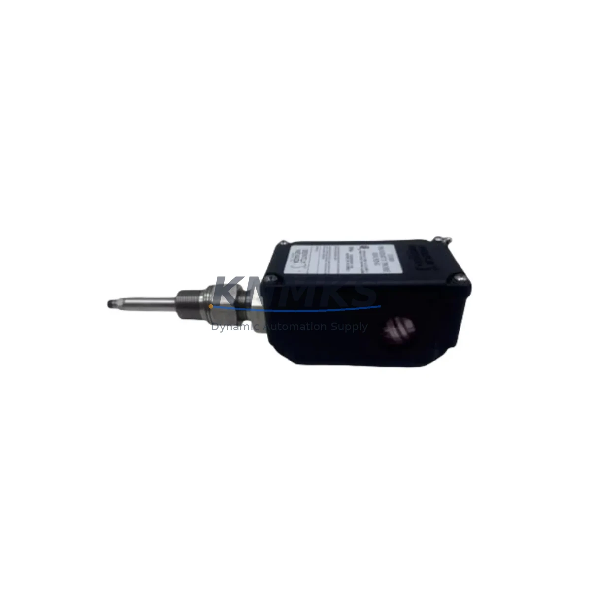
Bently Nevada 32000-29-05-10-075-07-02 Migration-Ready Proximity Probe: Legacy System Retrofit & Compatibility Upgrade
The Bently Nevada 32000-29-05-10-075-07-02 is a migration-ready proximity probe housing engineered for direct integration into existing 31000 and 32000 Series vibration monitoring control systems. As legacy Bently Nevada platforms approach end-of-life and OEM support windows close, plant engineers and reliability teams face increasing pressure to source verified replacement components that maintain signal integrity, mechanical fit, and system compatibility without requiring full platform overhauls. This unit addresses that challenge directly — providing a drop-in replacement path that preserves existing wiring, probe driver configurations, and Keyphasor signal chains while extending the operational life of installed monitoring infrastructure.
Whether you are managing a turbomachinery protection system, a compressor train monitoring rack, or a rotating equipment surveillance network built on the 3300 or 3500 Series monitoring platform, the 32000-29-05-10-075-07-02 probe housing is designed to slot into your existing installation with minimal field modification. The probe tip geometry, cable length, and connector interface are matched to the original specification, reducing the risk of signal offset errors that can arise when non-OEM-equivalent components are substituted without dimensional verification.
Migration Compatibility Table
| Parameter | 32000-29-05-10-075-07-02 | Legacy 31000 Series Reference |
|---|---|---|
| Probe Type | Eddy Current Proximity Probe | Eddy Current Proximity Probe |
| Tip Diameter | 8 mm (standard) | 8 mm |
| Cable Length | 7.5 m (per SKU suffix -075) | Variable — verify against existing routing |
| Connector Interface | BNC / MIL-spec per 32000 standard | Compatible — confirm driver input impedance |
| Driver Compatibility | 3300 XL / 3500 Series drivers | Verify 3300/3500 driver firmware revision |
| Mounting Thread | M10 x 1 (standard) | M10 x 1 — no bracket modification required |
| Installation Clearance | Confirm radial gap: 0.25–2.54 mm nominal | Re-gap after installation; do not assume prior gap is retained |
| Communication / Signal | Analog voltage output (–24 VDC bias) | Compatible with existing 3300/3500 monitor inputs |
| Replacement Recommendation | Direct replacement for 32000-29 series variants | Cross-reference -05-10-075-07-02 suffix for exact match |
| Commissioning Focus | Gap voltage verification, signal noise floor check | Re-calibrate after probe swap; do not reuse prior gap settings |
| Support terms | 12 Months | — |
Retrofit Planning for Existing Automation Systems
Successful integration of the 32000-29-05-10-075-07-02 into a legacy monitoring system requires a structured pre-installation review. Before removing the existing probe, engineers should document the current gap voltage reading at the 3300 XL 8 mm Proximity Transducer System driver or the equivalent 3500/42M Proximitor Monitor input card. This baseline reading is essential for post-installation verification and ensures that the replacement probe is operating within the linear range of the driver output curve.
Cable routing should be inspected prior to installation. The 7.5-metre cable length specified in the SKU suffix (-075) must be confirmed against the physical distance from the probe mounting boss to the driver input terminal in the monitoring rack. If the existing installation uses an extension cable — a common configuration in large turbine pedestals where the probe-to-rack distance exceeds standard cable lengths — the 3300 XL Extension Cable assembly must be verified for continuity and connector integrity before reuse. Substituting a new probe into a degraded extension cable assembly will produce erratic gap voltage readings that can be misdiagnosed as probe failure.
At the monitoring rack, the 3500 Series Rack Interface Module and the associated I/O module terminal assignments should be reviewed against the plant loop drawing set. Terminal block wiring for the probe common, positive drive, and signal return conductors must match the driver input wiring diagram. If the control system was originally commissioned with a 3300 Series rack and has since been partially migrated to a 3500 Series platform, the channel configuration in the 3500 Rack Configuration Software must reflect the correct transducer type and scale factor for the 32000-series probe to ensure that the vibration amplitude display on the associated System 1 Condition Monitoring Software or HMI screen is accurate.
For installations where the monitoring rack also interfaces with a DCS or safety instrumented system via a 3500/92 Communication Gateway Module, the Modbus or OPC-DA tag mapping for the affected channel should be verified before the probe is swapped. A probe replacement that changes the channel signal scaling — even temporarily during commissioning — can trigger spurious high-vibration alarms at the DCS level if the gateway tag scaling is not locked out during the maintenance window.
Physical installation space should be confirmed before ordering. The 32000-29-05-10-075-07-02 probe body dimensions are consistent with the 32000 Series standard, but bearing housing access, pedestal cover clearance, and the proximity of adjacent instrumentation — such as a Keyphasor probe mounted on the same shaft — must be assessed to confirm that the replacement probe can be installed and gapped without disturbing neighbouring sensors.
Downtime Control During System Migration
Minimising unplanned downtime during a proximity probe replacement requires pre-staging all replacement components and verifying their condition before the maintenance window opens. The 32000-29-05-10-075-07-02 unit supplied by KNMKS is function-tested prior to shipment, with gap voltage output verified against the 3300 XL driver calibration curve. This pre-shipment testing reduces the risk of receiving a non-functional component that cannot be identified until the machine is already offline.
During the replacement window, the original program logic in the 3500 Series rack should not be modified unless a firmware update is being applied concurrently. Changing probe hardware while simultaneously updating the 3500 Rack Configuration Software introduces multiple variables that complicate fault isolation if a signal anomaly is detected during post-installation commissioning. The recommended approach is to complete the mechanical probe swap and gap verification first, confirm stable gap voltage at the driver output, and only then proceed with any firmware or configuration changes.
If the plant safety system requires the vibration monitoring channel to be in a bypassed state during the probe swap, the bypass should be formally documented in the permit-to-work system and the bypass timer should be set to the minimum duration required for the mechanical work and gap verification. Leaving a vibration channel in bypass for an extended period while other commissioning tasks are completed increases the risk of an undetected machinery fault during the transition period.
Post-installation, the gap voltage should be recorded at the driver output terminal and compared against the pre-removal baseline. A deviation of more than ±0.5 VDC from the original gap voltage — after accounting for any intentional re-gapping — should be investigated before the machine is returned to service. The System 1 trend data for the affected channel should be reviewed to confirm that the vibration amplitude and phase readings are consistent with the machine historical baseline before the maintenance window is closed.
Retrofit Support FAQ
Q: Is the 32000-29-05-10-075-07-02 a direct replacement for my existing 31000 Series probe without any wiring changes?
A: In most installations, yes. The 32000-29-05-10-075-07-02 is designed as a drop-in replacement for 31000 and 32000 Series proximity probes with matching tip diameter, cable length, and connector interface. However, you should verify the driver input impedance and confirm that the extension cable — if used — is compatible before installation. KNMKS can provide a compatibility confirmation based on your existing part number and driver model.
Q: What commissioning steps are required after installing the replacement probe?
A: After mechanical installation, the air gap between the probe tip and the target shaft must be set to the nominal value specified in the original installation drawing (typically 1.0–1.5 mm for 8 mm probes). The gap voltage at the driver output should then be measured and recorded. The 3500 Series monitor channel should be taken out of bypass and the vibration amplitude and phase readings verified against the machine historical baseline before the machine is returned to service.
Q: Does KNMKS test the 32000-29-05-10-075-07-02 before shipment?
A: Yes. Each unit is function-tested against a 3300 XL driver prior to shipment to verify gap voltage output within the specified linear range. A test report is available on request. All units are covered by a support terms confirmed by quotation from the date of shipment.
Q: What is the typical lead time and do you maintain stock of this part?
A: KNMKS maintains inventory of the 32000-29-05-10-075-07-02 to support urgent replacement requirements. Standard lead time for in-stock units is 3–5 business days for international shipments. For time-critical shutdowns, expedited shipping options are available. Contact our team to confirm current stock availability before placing your order.
© 2026 KNMKS. All rights reserved.
Original Source: https://knmks.com
Contact: admin@knmks.com | +86 18359268345
Product Identification
- Brand / Ecosystem
-
Bently Nevada
Bently Nevada - Model / Series
- 32000-29-05-10-075-07-02
- Product Family
- Sensors
- Availability Status
- Available on request after model and quantity confirmation
- Inquiry Type
- B2B RFQ, replacement inquiry and project spare-part request
- Pre-Quote Check
- Exact SKU, brand, series, quantity, nameplate photos and destination country are checked before quotation
System Path
Where this product fits in the KNMKS automation structure.
Specification & Inquiry Focus
- Sensor range
- Photoelectric, proximity and process sensors
- Common needs
- Output type, distance and connector
- Project support
- Machine detection and replacement inquiry
Buyer Confirmation
Information KNMKS checks before replying.
- Exact model
- 32000-29-05-10-075-07-02
- Brand / ecosystem
- Bently Nevada
- Product family
- Sensors
- Application note
- Replacement, maintenance, project build or spare-part list
- Useful photos
- Nameplate, installed unit, cabinet layout or connector side
- Delivery details
- Quantity, destination country and target schedule
Document Support
Files and notes can be confirmed during quotation.
- Product photos or nameplate confirmation when available
- Packing and delivery notes before quotation confirmation
- Support scope and delivery terms confirmed per inquiry
- Export document coordination for qualified B2B requests
Inquiry Support
- NPN/PNP, analog and digital output checking
- Connector and cable compatibility review
- Fast inquiry support for maintenance teams
What to Send Us
- Brand and exact model number: Bently Nevada 32000-29-05-10-075-07-02
- Quantity and required delivery time
- Application, replacement requirement or nameplate photo
- Destination country and shipping preference
RFQ Preparation
This is a product inquiry page built for RFQ communication.
Fast Model Check
Send this model to KNMKS for confirmation.
Include quantity, destination country and photos if this is a maintenance replacement. The inquiry will be saved with a reference number after submission.
Brand & Compatibility Note
KNMKS displays automation product information for well-known industrial brand ecosystems and compatible replacement references. Brand names are used for product identification and compatibility reference only; final availability and commercial terms are confirmed per quotation.
 Manufacturing
 Machine Tools
 Packaging
 Energy & Power

 PLCs & Controllers
 HMI & Displays
 Servo Systems
 Variable Frequency Drives