
Overview
Bently Nevada 21508-02-12-05-02 Migration-Ready Proximity Probe for Legacy Vibration Monitoring Systems
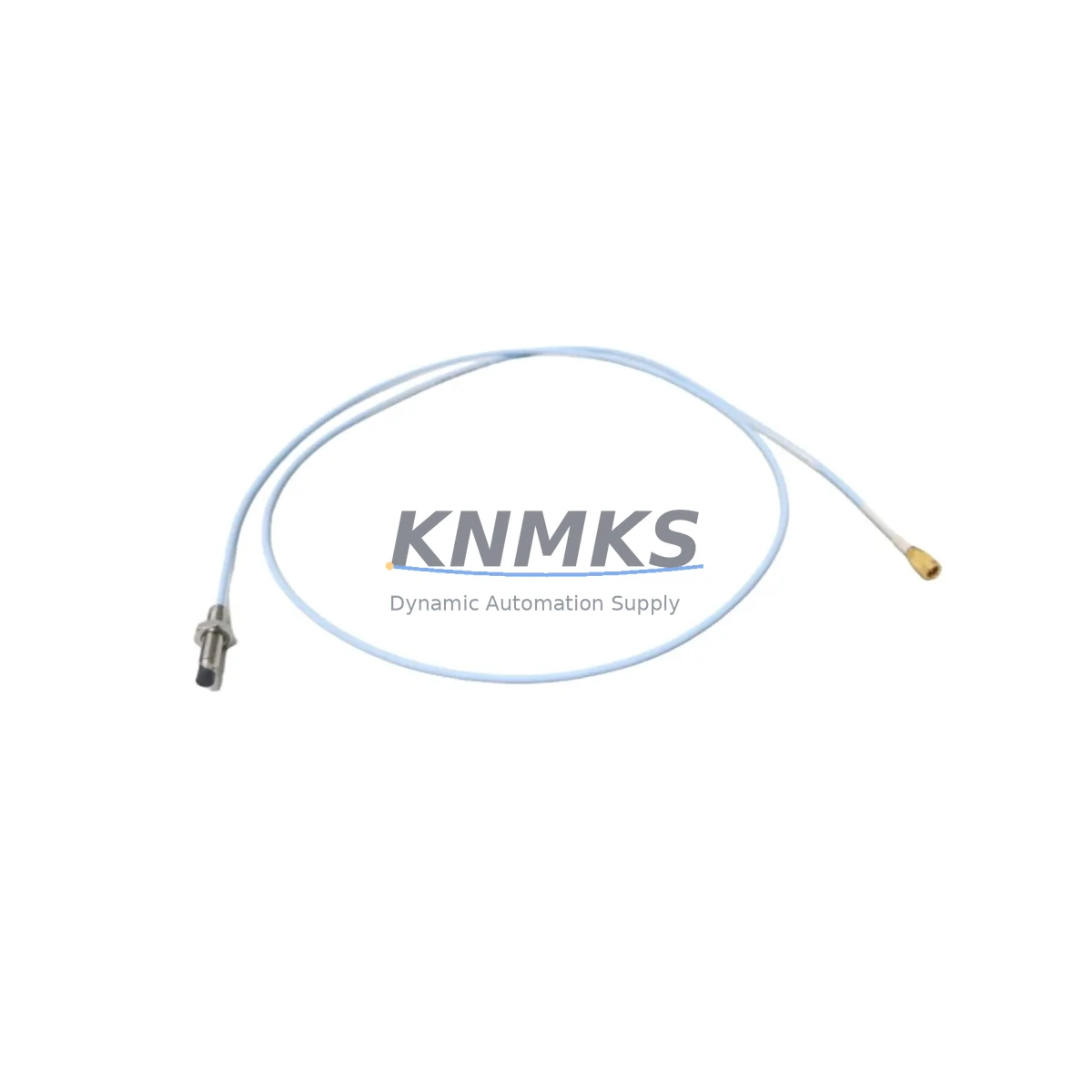
The Bently Nevada 21508-02-12-05-02 is a 5mm eddy-current proximity probe engineered for direct replacement and retrofit integration within legacy Bently Nevada 21508 Series vibration monitoring installations. As rotating machinery protection systems age and original spare parts become increasingly scarce, the 21508-02-12-05-02 provides a verified migration path that preserves existing wiring infrastructure, signal conditioning chains, and System 1 software configurations without requiring full panel redesign. This probe is stocked for immediate dispatch and ships with a support terms confirmed by quotation and pre-shipment functional verification.
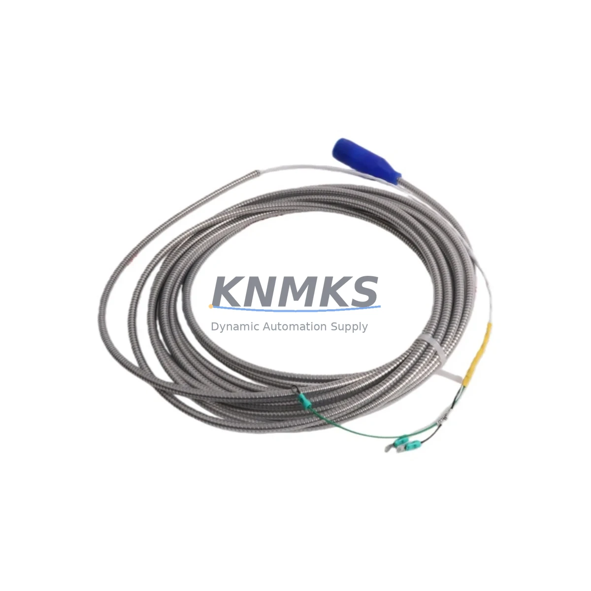
Facilities operating turbines, compressors, pumps, and gearboxes under continuous monitoring programs frequently encounter the challenge of sourcing replacement probes when the original 21508 Series components reach end-of-life. The 21508-02-12-05-02 addresses this directly: its 5mm sensing tip, 200 mV/mil output sensitivity, and standard Bently Nevada connector interface allow it to be installed into existing probe holders and extension cable assemblies — including the 330130 Series extension cables — without recalibrating the paired 3300 XL proximitor or rewriting gap voltage setpoints in the monitoring rack.
Before installation, maintenance engineers should confirm the existing proximitor supply voltage (typically –24 VDC), verify the probe-to-target gap voltage falls within the linear range (typically –10 VDC at 50 mil gap), and inspect the extension cable for continuity and shield integrity. The 330130-080-00-00 extension cable and 3300 XL 8mm proximitor are common companion components in these installations; if the proximitor is also being replaced as part of a broader 3300 Series rack upgrade, the gap voltage calibration procedure must be repeated at the new proximitor before returning the loop to service.
Migration Compatibility Table
| Parameter | 21508-02-12-05-02 (This Unit) | Legacy / Replaced Model | Migration Note |
|---|---|---|---|
| Probe Tip Diameter | 5 mm | 5 mm (21508 Series) | Direct fit — no probe holder modification required |
| Output Sensitivity | 200 mV/mil | 200 mV/mil | Gap voltage setpoints remain valid; no recalibration of monitor required |
| Supply Voltage | –24 VDC (nominal) | –24 VDC | Confirm proximitor supply rail before installation |
| Connector Interface | Standard BN coaxial | Standard BN coaxial | Compatible with 330130 Series extension cables |
| Proximitor Compatibility | 3300 XL Series, 3300 Series | 3300 XL / 3300 Series | Verify proximitor firmware version if rack was recently updated |
| Monitoring Rack Interface | 3500 Series rack / 3300 rack | 3500 / 3300 Series | No I/O card changes required for direct probe swap |
| Installation Space | Standard 21508 probe body dimensions | 21508 Series body | Confirm probe holder thread and body length before ordering |
| Support terms | 12 Months | — | Includes pre-shipment functional test certificate |
Retrofit Planning for Existing Automation Systems
A successful retrofit of the 21508-02-12-05-02 into an operating machinery protection system requires a structured review of the full signal chain — not just the probe itself. In most 3500 Series rack installations, the proximity probe loop consists of the probe, a 330130 Series extension cable, and a 3300 XL proximitor module mounted in the rack. Each element must be assessed before the replacement probe is installed.
Begin by documenting the existing gap voltage at the proximitor output terminal. This baseline reading — typically recorded in the machinery protection system’s commissioning report — serves as the acceptance criterion after the new 21508-02-12-05-02 is installed and gapped. If the 3300 XL proximitor itself is showing drift or has accumulated operating hours beyond its recommended service interval, this is an appropriate time to replace it alongside the probe, using a current-production 3300 XL 5mm proximitor to maintain system consistency.
For facilities running System 1 Evolution software, the probe channel configuration — including full-scale range, alert and danger setpoints, and transducer scale factor — is stored at the rack level in the 3500/42M Proximitor/Seismic Monitor card. These parameters do not need to be modified for a like-for-like probe replacement, but the configuration should be exported and archived before any work begins. If the retrofit is part of a broader control system upgrade that includes replacing the 3500/42M card or migrating to a newer I/O architecture, the System 1 database export becomes a critical recovery document.
In installations where the proximity probe monitors radial vibration on a steam turbine or centrifugal compressor, the signal is often cross-referenced with a Keyphasor signal from a separate 3500/25 Keyphasor Module. Confirm that the Keyphasor channel remains active and correctly phased after the probe swap, as any disruption to the once-per-revolution reference signal will affect vibration vector calculations and trend data continuity in System 1. Additionally, if the machine train includes a thrust position channel using a 3300 XL 8mm proximitor and a separate 21508 Series thrust probe, inspect that channel simultaneously to avoid a second planned outage in the near term.
Downtime Control During System Migration
Minimizing unplanned downtime during a proximity probe replacement on a critical rotating machine requires preparation that begins well before the maintenance window opens. The 21508-02-12-05-02 should be bench-tested against a known-good proximitor before the outage to confirm output linearity across the full gap range. This pre-installation verification — part of the standard pre-shipment test protocol for this unit — eliminates the risk of discovering a probe defect after the machine has been taken offline.
During the outage, the replacement sequence should follow a defined procedure: isolate the channel at the 3500 rack I/O module, disconnect the extension cable at the proximitor, remove the probe from the holder, install the 21508-02-12-05-02, reconnect the extension cable, restore power to the proximitor, and measure the gap voltage before re-enabling the channel. This sequence preserves the original program logic in the 3500 rack and avoids inadvertent alarm trips during the swap. The 3500 rack’s bypass function should be used to suppress alerts on the affected channel during the procedure, with the bypass state logged in the maintenance record.
For facilities with redundant monitoring channels — common on API 670-compliant installations — the redundant channel can remain active during the swap, maintaining continuous protection on the machine. Once the replacement probe is gapped and the channel is re-enabled, compare the two channel readings to confirm agreement within the expected tolerance before releasing the machine to operations. This approach reduces effective downtime to the duration of the physical probe swap and gap adjustment, typically under 30 minutes for an accessible probe location.
Retrofit Support FAQ
Q1: Is the 21508-02-12-05-02 a direct replacement for all 21508 Series proximity probes?
The 21508-02-12-05-02 is a direct replacement for 21508 Series probes with matching body length (02 = 2-inch), cable length (12 = 12-inch integral cable), and tip diameter (05 = 5mm). Confirm the full part number suffix against your existing probe before ordering. Probes with different body or cable length codes require verification of probe holder dimensions and extension cable length to maintain the correct system length for the paired proximitor.
Q2: Do I need to recalibrate the 3300 XL proximitor after installing this probe?
For a direct like-for-like replacement using the same system length, recalibration of the 3300 XL proximitor is not required. The gap voltage should be re-verified at the target gap distance specified in the original commissioning report. If the measured gap voltage deviates from the baseline by more than ±0.5 VDC, inspect the extension cable for damage and confirm the probe-to-target material matches the original installation (typically AISI 4140 steel).
Q3: What commissioning checks are required after installation?
After installing the 21508-02-12-05-02, perform the following: (1) measure and record the gap voltage at the proximitor output; (2) confirm the reading falls within the linear range specified on the proximitor calibration curve; (3) verify that the 3500 rack channel is reading correctly in System 1 and that no latched alerts are present; (4) compare readings against the adjacent redundant channel if applicable; (5) remove any channel bypasses and log the completion in the maintenance management system.
Q4: What support terms and stock availability does this unit carry?
The 21508-02-12-05-02 is supplied with a support terms confirmed by quotation covering manufacturing defects and functional performance. Each unit undergoes pre-shipment functional testing before dispatch. Stock is maintained for immediate availability to support emergency replacement and planned maintenance programs. Contact admin@knmks.com or +86 18359268345 for lead time confirmation and volume pricing.
© 2026 KNMKS. All rights reserved.
Original Source: https://knmks.com
Contact: admin@knmks.com | +86 18359268345
Product Identification
- Brand / Ecosystem
-
Bently Nevada
Bently Nevada - Model / Series
- 21508-02-12-05-02
- Product Family
- Sensors
- Availability Status
- Available on request after model and quantity confirmation
- Inquiry Type
- B2B RFQ, replacement inquiry and project spare-part request
- Pre-Quote Check
- Exact SKU, brand, series, quantity, nameplate photos and destination country are checked before quotation
System Path
Where this product fits in the KNMKS automation structure.
Specification & Inquiry Focus
- Sensor range
- Photoelectric, proximity and process sensors
- Common needs
- Output type, distance and connector
- Project support
- Machine detection and replacement inquiry
Buyer Confirmation
Information KNMKS checks before replying.
- Exact model
- 21508-02-12-05-02
- Brand / ecosystem
- Bently Nevada
- Product family
- Sensors
- Application note
- Replacement, maintenance, project build or spare-part list
- Useful photos
- Nameplate, installed unit, cabinet layout or connector side
- Delivery details
- Quantity, destination country and target schedule
Document Support
Files and notes can be confirmed during quotation.
- Product photos or nameplate confirmation when available
- Packing and delivery notes before quotation confirmation
- Support scope and delivery terms confirmed per inquiry
- Export document coordination for qualified B2B requests
Inquiry Support
- NPN/PNP, analog and digital output checking
- Connector and cable compatibility review
- Fast inquiry support for maintenance teams
What to Send Us
- Brand and exact model number: Bently Nevada 21508-02-12-05-02
- Quantity and required delivery time
- Application, replacement requirement or nameplate photo
- Destination country and shipping preference
RFQ Preparation
This is a product inquiry page built for RFQ communication.
Fast Model Check
Send this model to KNMKS for confirmation.
Include quantity, destination country and photos if this is a maintenance replacement. The inquiry will be saved with a reference number after submission.
Brand & Compatibility Note
KNMKS displays automation product information for well-known industrial brand ecosystems and compatible replacement references. Brand names are used for product identification and compatibility reference only; final availability and commercial terms are confirmed per quotation.
 Manufacturing
 Machine Tools
 Packaging
 Energy & Power

 PLCs & Controllers
 HMI & Displays
 Servo Systems
 Variable Frequency Drives