
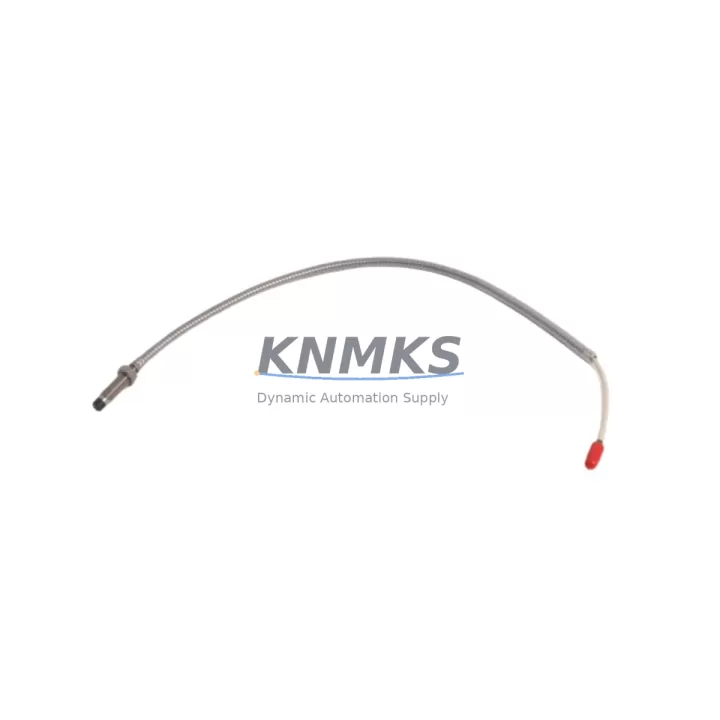
Overview
Bently Nevada 21505-00-60-10-02 Maintenance Spare Part for Factory Uptime
The Bently Nevada 21505-00-60-10-02 is a precision proximity signal conditioner designed for continuous operation within the 3500 Series machinery protection system. As a maintenance-proven spare part, it plays a critical role in vibration monitoring, radial shaft displacement measurement, and machinery health surveillance across turbines, compressors, pumps, and rotating equipment in oil & gas, power generation, petrochemical, and heavy industrial facilities. Sourced as an original Bently Nevada component, this unit is fully tested prior to shipment and backed by a support terms confirmed by quotation, ensuring your maintenance team can restore system integrity with confidence and minimal downtime.
For maintenance engineers managing aging 3500 Series racks, the 21505-00-60-10-02 is a direct replacement for failed or degraded proximity signal conditioners. Its compatibility with standard Bently Nevada 3500 backplane architecture means no firmware reconfiguration is required in most installations, significantly reducing the time from fault isolation to system restoration. Procurement engineers can rely on our long-term supply commitment and tested-before-shipment protocol to reduce incoming inspection burden and accelerate return-to-service timelines.
Spare Maintenance Table
| Parameter | Specification / Detail |
|---|---|
| Part Number | 21505-00-60-10-02 |
| Brand | Bently Nevada |
| Series | 3500 Machinery Protection System |
| Module Type | Proximity Signal Conditioner |
| Input Signal | Proximitor / Eddy-Current Probe (Bently Nevada compatible) |
| Output Signal | 4–20 mA / Voltage (series-dependent configuration) |
| Supply Voltage | –24 VDC (nominal, via 3500 backplane) |
| Measurement Type | Radial vibration, axial position, shaft displacement |
| Compatibility | Bently Nevada 3500 Series rack, standard backplane |
| Installation | Plug-in module, 3500 rack slot |
| Operating Temperature | 0°C to +60°C (standard industrial environment) |
| Application | Turbines, compressors, pumps, fans, rotating machinery |
| Origin | United States |
| Condition | Original spare, tested before shipment |
| Support terms | 12 months from date of shipment |
| Lead Time | availability confirmed by RFQ — ships within 1–3 business days |
Maintenance Planning for Continuous Operation
When replacing the 21505-00-60-10-02 proximity signal conditioner in a 3500 Series rack, a thorough site inspection of the surrounding electrical and signal infrastructure is essential to prevent repeat failures and ensure long-term system reliability. Maintenance engineers should begin by verifying the integrity of the 3500/15 Power Supply Module, as an unstable or degraded rack power supply is a common root cause of signal conditioner failure. Confirm that the –24 VDC backplane voltage is within specification before inserting the replacement module.
Next, inspect the Proximitor sensor and interconnecting cable (typically a 3300 XL or 7200 Series Proximitor) for cable damage, connector corrosion, or gap voltage drift. A faulty probe or cable will immediately stress the new signal conditioner. Check the 3500/20 Rack Interface Module (RIM) for communication integrity, as this module manages the data highway between the 3500 rack and the host DCS or historian. If the RIM shows any fault LED, address it concurrently to avoid masking alarms post-replacement.
For installations with relay output requirements, inspect the 3500/32 4-Channel Relay Module to confirm that trip setpoints and relay logic remain correctly configured after the signal conditioner swap. In systems where the 3500 rack feeds a DCS I/O card or safety PLC input, verify that the 4–20 mA loop is intact and that the receiving card registers the correct engineering-unit value after module insertion. Terminal blocks and field wiring connections at the I/O terminal board should be torqued to specification and inspected for oxidation, particularly in humid or offshore environments.
Where signal isolation is required between the 3500 rack output and the control room DCS, a signal isolator or loop-powered isolator in the signal path should be tested for correct pass-through accuracy. Finally, confirm that the 3500/05 System Display and Keyboard Module (or equivalent HMI interface) correctly reflects the new module’s channel data and that no latched alarms remain from the previous fault condition. A complete functional test — including a simulated vibration input and alarm verification — should be performed before returning the machine to service.
Site Replacement Workflow
Step 1 — Fault Isolation: Use the 3500 rack’s front-panel LED indicators and the System Display Module to identify the faulted signal conditioner slot. Log the channel number, measured gap voltage, and any active alarms before removing the module.
Step 2 — Safe Removal: Follow your site’s lockout/tagout (LOTO) procedure if required. The 3500 Series supports hot-swap of signal conditioner modules in most configurations — confirm with your site safety plan. Carefully extract the 21505-00-60-10-02 from its rack slot using the module ejector levers.
Step 3 — Visual Inspection: Before inserting the replacement unit, inspect the rack slot connector for bent pins, debris, or corrosion. Clean with approved contact cleaner if necessary.
Step 4 — Module Insertion: Insert the replacement 21505-00-60-10-02 firmly into the rack slot until the ejector levers click into place. Verify that the module’s PWR LED illuminates and that no FAULT LED is active.
Step 5 — Configuration Verification: Using the 3500 Configuration Software or the System Display Module, confirm that the channel configuration (transducer type, full-scale range, alarm setpoints) matches the previous module’s settings. No re-configuration should be required if the replacement module is of the same part number.
Step 6 — Functional Test: Apply a known gap voltage to the Proximitor input and verify that the signal conditioner outputs the correct 4–20 mA value. Confirm that OK relay, alert, and danger setpoints respond correctly. Document the test results in your maintenance management system (CMMS).
Step 7 — Return to Service: Clear any latched alarms, restore normal monitoring mode, and notify the control room that the channel is back in service. Update your spare parts inventory to reflect the consumed unit and initiate a replenishment order to maintain your critical spare buffer.
Spare Parts Support FAQ
Q1: Is the 21505-00-60-10-02 a direct drop-in replacement for the existing module in my 3500 rack?
Yes. The 21505-00-60-10-02 is designed as a slot-compatible replacement within the Bently Nevada 3500 Series rack architecture. In most installations, no reconfiguration is required, as the module reads its channel configuration from the rack’s non-volatile memory. We recommend verifying configuration via the 3500 Configuration Software after insertion as a best practice.
Q2: How is the unit tested before shipment?
Every 21505-00-60-10-02 unit we supply undergoes a functional test that includes power-on verification, output signal accuracy check, and LED status confirmation. Units that do not pass our pre-shipment test protocol are not dispatched. A test report is available upon request for quality-critical procurement processes.
Q3: What does the support terms confirmed by quotation cover?
The support terms confirmed by quotation cover manufacturing defects and functional failures under normal operating conditions from the date of shipment. It does not cover damage resulting from incorrect installation, overvoltage, or physical mishandling. Our after-sales team at admin@knmks.com will coordinate support terms assessment and replacement logistics promptly.
Q4: Can you support long-term or blanket orders for this part number?
Yes. We maintain dedicated stock of the 21505-00-60-10-02 and can support blanket purchase orders, annual maintenance contracts, and scheduled delivery programs. Long-term supply agreements help maintenance teams avoid emergency procurement premiums and ensure critical spare availability for planned shutdowns and annual overhauls. Contact us at admin@knmks.com or +86 18359268345 to discuss your supply requirements.
© 2026 KNMKS. All rights reserved.
Original Source: https://knmks.com
Contact: admin@knmks.com | +86 18359268345
Product Identification
- Brand / Ecosystem
-
Bently Nevada
Bently Nevada - Model / Series
-
21505-00-60-10-02
3500 Series - Product Family
- Other Components
- Availability Status
- Available on request after model and quantity confirmation
- Inquiry Type
- B2B RFQ, replacement inquiry and project spare-part request
- Pre-Quote Check
- Exact SKU, brand, series, quantity, nameplate photos and destination country are checked before quotation
System Path
Where this product fits in the KNMKS automation structure.
Specification & Inquiry Focus
- Component range
- Breakers, terminals and cabinet accessories
- Common needs
- Model, photo and installation requirement
- Project support
- Maintenance and mixed spare-part inquiry
Buyer Confirmation
Information KNMKS checks before replying.
- Exact model
- 21505-00-60-10-02
- Brand / ecosystem
- Bently Nevada
- Product family
- Other Components
- Application note
- Replacement, maintenance, project build or spare-part list
- Useful photos
- Nameplate, installed unit, cabinet layout or connector side
- Delivery details
- Quantity, destination country and target schedule
Document Support
Files and notes can be confirmed during quotation.
- Product photos or nameplate confirmation when available
- Packing and delivery notes before quotation confirmation
- Support scope and delivery terms confirmed per inquiry
- Export document coordination for qualified B2B requests
Inquiry Support
- Mixed automation spare parts inquiry
- Cabinet component and accessory support
- Model identification from photos or labels
What to Send Us
- Brand and exact model number: Bently Nevada 21505-00-60-10-02
- Quantity and required delivery time
- Application, replacement requirement or nameplate photo
- Destination country and shipping preference
RFQ Preparation
This is a product inquiry page built for RFQ communication.
Fast Model Check
Send this model to KNMKS for confirmation.
Include quantity, destination country and photos if this is a maintenance replacement. The inquiry will be saved with a reference number after submission.
Brand & Compatibility Note
KNMKS displays automation product information for well-known industrial brand ecosystems and compatible replacement references. Brand names are used for product identification and compatibility reference only; final availability and commercial terms are confirmed per quotation.
 Manufacturing
 Machine Tools
 Packaging
 Energy & Power
 PLCs & Controllers
 HMI & Displays
 Servo Systems
 Variable Frequency Drives