
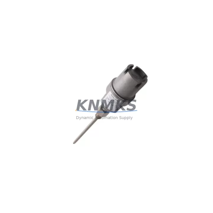
Overview
Bently Nevada 21000-16-05-15-062-03-02 Maintenance-Proven Spare Part for Factory Uptime
The Bently Nevada 21000-16-05-15-062-03-02 is a critical vibration monitoring module within the 3500 Series machinery protection system — one of the most widely deployed continuous monitoring platforms in rotating equipment applications across oil & gas, power generation, petrochemical, and heavy industrial facilities. When this module fails or reaches end-of-service life, the consequences extend beyond a single measurement channel: the entire protection loop for a turbine, compressor, or pump train may be compromised, triggering unplanned shutdowns or, worse, undetected mechanical degradation.
At KNMKS, every 21000-16-05-15-062-03-02 unit is sourced from verified supply channels, subjected to pre-shipment functional inspection, and backed by a support terms confirmed by quotation. Whether you are executing a planned annual overhaul, responding to a trip event, or building a strategic spare parts buffer for a remote facility, this module ships with full traceability documentation to support your maintenance records and site acceptance procedures.
Maintenance engineers and reliability teams operating 3500 Series racks recognize that the 21000-16-05-15-062-03-02 does not operate in isolation. Its performance depends on the integrity of the surrounding system architecture — from the rack power supply and backplane interconnects to the I/O termination assemblies and the communication path to the host monitoring system. A disciplined replacement workflow addresses all of these touch points simultaneously.
Spare Maintenance Table
| Parameter | Specification / Recommendation |
|---|---|
| Part Number | 21000-16-05-15-062-03-02 |
| Brand | Bently Nevada |
| Series | 3500 Series Machinery Protection System |
| Module Type | Vibration Monitoring Module |
| Compatibility | 3500 Series rack systems; back-to-back compatible with equivalent 3500 monitor slots |
| Input Channels | Per OEM configuration (typically 2-channel or 4-channel vibration input) |
| Signal Type | Proximity probe / velocity / accelerometer inputs (configuration-dependent) |
| Power Supply | Supplied via 3500 rack backplane (3500/15 or 3500/05 power supply module) |
| Communication | Rack backplane bus; optional Modbus/TCP or System 1 integration via gateway |
| Operating Temperature | 0°C to +60°C (32°F to 140°F) |
| Mounting | 3500 Series rack slot (standard 19-inch rack) |
| Support terms | 12 Months — KNMKS Tested & Verified |
| Origin | United States |
| Lead Time | In-stock; ships within 1–3 business days |
| Maintenance Interval | Inspect annually or upon alarm/trip event; replace per condition-based assessment |
Maintenance Planning for Continuous Operation
Replacing the 21000-16-05-15-062-03-02 is rarely a standalone task. Experienced maintenance engineers treat a module swap as an opportunity to audit the full measurement chain and associated protection infrastructure. Before returning the rack to service, the following components and subsystems warrant inspection or staged replacement as part of the same work order.
The 3500/15 Power Supply Module or 3500/05 Rack Power Supply should be verified for output voltage stability and ripple within OEM tolerance. A degraded power supply is a common root cause of intermittent module faults and nuisance trips; replacing the vibration monitor without confirming power integrity risks a repeat failure within weeks. Similarly, the 3500 Series backplane connector pins and card-edge contacts should be inspected for oxidation, fretting corrosion, or mechanical damage — particularly in high-vibration or high-humidity environments.
On the field wiring side, the 3500/20 Rack Interface Module or equivalent termination assembly connects the 21000-16-05-15-062-03-02 to the proximity probe drivers, velocity transducers, or accelerometers installed on the rotating equipment. Inspect the termination block for loose screws, corroded terminals, and shield grounding continuity. Probe cable integrity — including the 3300 XL 8mm or 5mm proximity transducer system cables and extension cables — should be confirmed with a loop resistance and gap voltage check before the new module is commissioned.
For facilities running System 1 Evolution or a third-party DCS integration, verify that the communication gateway module (such as the 3500/92 Communication Gateway) is correctly configured and that the new module’s slot address and channel assignments match the historian tag mapping. A mismatch here will result in silent data loss — the protection system may be operational while the condition monitoring database receives no valid data.
Finally, review the relay output modules (such as the 3500/32 Relay Module) associated with the trip and alarm outputs driven by this monitor. Relay contact wear, coil resistance drift, and wiring integrity at the relay terminal strips are common failure points that surface only when the protection system is exercised during a real event. Confirming relay function during a planned outage is far preferable to discovering a failed relay during an emergency trip.
Site Replacement Workflow
A structured replacement workflow for the 21000-16-05-15-062-03-02 minimizes downtime and ensures the system is returned to a fully verified state before the protected equipment is restarted.
Step 1 — Pre-Outage Preparation: Confirm the replacement module part number matches the installed configuration, including any firmware or configuration suffix variants. Download the existing module configuration from the rack using Rack Configuration Software (RCS) or System 1 before removing the old module. Retain this configuration file as the baseline for the new module.
Step 2 — Safe Isolation: Coordinate with operations to place the protected machine in a safe state. Bypass the trip outputs at the relay module level (not at the field device) to prevent spurious trips during the swap. Document the bypass in the permit-to-work system.
Step 3 — Module Removal and Inspection: Remove the 21000-16-05-15-062-03-02 from the rack slot. Inspect the slot connector, backplane, and adjacent modules for signs of heat damage, contamination, or mechanical stress. Clean the slot with dry compressed air if required.
Step 4 — New Module Installation and Configuration: Insert the replacement module and restore the saved configuration via RCS. Verify that all channel parameters — full-scale range, alert and danger setpoints, time delays, and OK relay logic — match the original settings. Do not rely on default factory parameters.
Step 5 — Functional Verification: Apply a known reference signal to each input channel using a calibrated signal simulator. Confirm that the module responds correctly to alert and danger thresholds and that the relay outputs operate as expected. Verify System 1 or DCS tag updates are received correctly.
Step 6 — Return to Service: Remove the trip bypass, confirm all OK indicators are active, and document the replacement in the equipment maintenance record. Update the spare parts inventory to reflect the consumed module and initiate a replenishment order to maintain buffer stock.
Spare Parts Support FAQ
Q1: Is the 21000-16-05-15-062-03-02 a direct drop-in replacement for older 3500 Series monitor modules?
A: The 21000-16-05-15-062-03-02 is designed for the 3500 Series rack architecture and is back-to-back compatible with equivalent monitor slots in the same series. However, configuration suffix variants may reflect differences in channel count, input type, or approval ratings. Always verify the full part number — including all suffix segments — against your installed module before ordering. KNMKS technical support can assist with compatibility confirmation prior to shipment.
Q2: What pre-shipment testing does KNMKS perform on this module?
A: Each unit undergoes a functional inspection covering power-up self-test, channel input response, and communication interface verification before dispatch. Units that do not pass inspection are not shipped. A support terms confirmed by quotation cover defects in materials and workmanship from the date of delivery, providing assurance for both planned maintenance and emergency replacement scenarios.
Q3: How should we manage long-term spare parts inventory for 3500 Series modules?
A: For facilities with multiple 3500 Series racks or critical rotating equipment, a minimum buffer of one spare per installed module type is recommended. For high-criticality applications — gas turbines, large centrifugal compressors, or main oil line pumps — a two-unit buffer is prudent given the potential for extended lead times on legacy or allocated parts. KNMKS maintains regional stock and can support blanket purchase agreements to lock in pricing and availability for multi-year maintenance programs.
Q4: Can KNMKS supply the 21000-16-05-15-062-03-02 on an ongoing basis for multi-year maintenance contracts?
A: Yes. KNMKS supports long-term supply agreements for 3500 Series spare parts, including the 21000-16-05-15-062-03-02. Our sourcing network covers both current-production and legacy-allocated components, and we can provide delivery commitments aligned with your annual overhaul schedule or condition-based replacement program. Contact our sales team to discuss volume pricing, lead time guarantees, and consignment stock options.
© 2026 KNMKS. All rights reserved.
Original Source: https://knmks.com
Contact: admin@knmks.com | +86 18359268345
Product Identification
- Brand / Ecosystem
-
Bently Nevada
Bently Nevada - Model / Series
-
21000-16-05-15-062-03-02
3500 Series - Product Family
- Other Components
- Availability Status
- Available on request after model and quantity confirmation
- Inquiry Type
- B2B RFQ, replacement inquiry and project spare-part request
- Pre-Quote Check
- Exact SKU, brand, series, quantity, nameplate photos and destination country are checked before quotation
System Path
Where this product fits in the KNMKS automation structure.
Specification & Inquiry Focus
- Component range
- Breakers, terminals and cabinet accessories
- Common needs
- Model, photo and installation requirement
- Project support
- Maintenance and mixed spare-part inquiry
Buyer Confirmation
Information KNMKS checks before replying.
- Exact model
- 21000-16-05-15-062-03-02
- Brand / ecosystem
- Bently Nevada
- Product family
- Other Components
- Application note
- Replacement, maintenance, project build or spare-part list
- Useful photos
- Nameplate, installed unit, cabinet layout or connector side
- Delivery details
- Quantity, destination country and target schedule
Document Support
Files and notes can be confirmed during quotation.
- Product photos or nameplate confirmation when available
- Packing and delivery notes before quotation confirmation
- Support scope and delivery terms confirmed per inquiry
- Export document coordination for qualified B2B requests
Inquiry Support
- Mixed automation spare parts inquiry
- Cabinet component and accessory support
- Model identification from photos or labels
What to Send Us
- Brand and exact model number: Bently Nevada 21000-16-05-15-062-03-02
- Quantity and required delivery time
- Application, replacement requirement or nameplate photo
- Destination country and shipping preference
RFQ Preparation
This is a product inquiry page built for RFQ communication.
Fast Model Check
Send this model to KNMKS for confirmation.
Include quantity, destination country and photos if this is a maintenance replacement. The inquiry will be saved with a reference number after submission.
Brand & Compatibility Note
KNMKS displays automation product information for well-known industrial brand ecosystems and compatible replacement references. Brand names are used for product identification and compatibility reference only; final availability and commercial terms are confirmed per quotation.
 Manufacturing
 Machine Tools
 Packaging
 Energy & Power
 PLCs & Controllers
 HMI & Displays
 Servo Systems
 Variable Frequency Drives