
Overview
Bently Nevada 200155-03-CN Migration-Ready Vibration Accelerometer for Legacy Control Systems
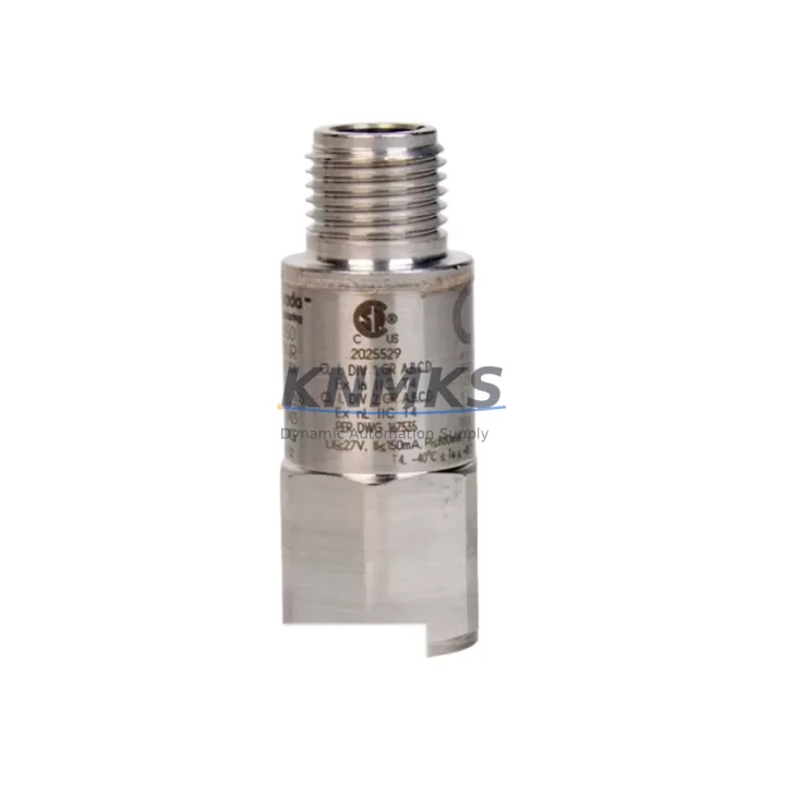
The Bently Nevada 200155-03-CN is a low-frequency vibration accelerometer engineered for direct retrofit into existing TrendMaster Pro and 3500 Series condition monitoring architectures. As legacy Bently Nevada platforms approach end-of-support milestones, maintenance engineers and reliability teams face increasing pressure to source verified replacement modules that preserve signal integrity, wiring compatibility, and system continuity without requiring full platform migration. The 200155-03-CN addresses this challenge by delivering back-to-back mechanical and electrical compatibility with the original accelerometer footprint, enabling controlled, low-risk upgrades across rotating machinery monitoring applications including turbines, compressors, pumps, and gearboxes.
When planning a retrofit around the 200155-03-CN, engineers must confirm several critical parameters before installation. Power supply capacity at the field junction box or DIN rail must support the accelerometer’s operating current draw, particularly in multi-channel installations where cumulative load can approach the output limits of the existing 3500/20 Power Supply module. Terminal wiring should be verified against the original loop drawing — the 200155-03-CN uses a standard two-wire IEPE (Integrated Electronics Piezo-Electric) interface, but polarity and shield grounding practices must match the existing cable run to avoid ground loop noise on the 3500/40M Monitor input. Backplane slot addressing and channel mapping within the 3500 rack must be confirmed in the System 1 configuration database before the replacement module is energized, as incorrect channel assignments will generate false alarm states on the connected HMI display or DCS faceplate.
Program logic compatibility is a key concern in any accelerometer swap. If the existing 3500/40M or 3500/42M monitor card has been configured with custom alarm setpoints, gap voltage thresholds, or integration filters for velocity output, those parameters must be exported from System 1 software and re-validated after the 200155-03-CN is installed. Communication link integrity between the 3500 rack and the upstream DCS — typically via Modbus RTU over RS-485 or Ethernet/IP through the 3500/92 Communication Gateway — should be tested under live process conditions before the legacy accelerometer is decommissioned. HMI screen tag assignments referencing the original sensor channel should be audited to confirm that trend displays, alarm banners, and historian tags continue to resolve correctly after the swap.
Installation space confirmation is straightforward for most applications: the 200155-03-CN retains the standard M8 mounting thread and compact cylindrical housing of the original TrendMaster Pro accelerometer family, making it compatible with existing mounting pads, magnetic bases, and adhesive mounting adapters already installed on the machine casing. Firmware version requirements on the 3500/40M monitor card should be checked against Bently Nevada’s compatibility matrix — units running firmware below revision 3.x may require a field update via the 3500 Rack Configuration Software before the new accelerometer’s sensitivity coefficient can be correctly applied.
Migration Compatibility Table
| Parameter | Legacy Reference | 200155-03-CN Specification | Retrofit Note |
|---|---|---|---|
| Mounting Interface | M8 threaded stud / adhesive pad | M8 threaded stud / adhesive pad | Direct drop-in; no adapter required |
| Electrical Interface | 2-wire IEPE, 18–30 VDC constant current | 2-wire IEPE, 18–30 VDC constant current | Verify existing cable polarity and shield grounding |
| Sensitivity | 100 mV/g (nominal) | 100 mV/g ±5% | Re-enter sensitivity coefficient in 3500/40M configuration |
| Frequency Range | 0.5 Hz – 2,000 Hz | 0.5 Hz – 2,000 Hz | Compatible with existing integration filter settings |
| Compatible Monitor Cards | 3500/40M, 3500/42M, TrendMaster Pro I/O | 3500/40M, 3500/42M, TrendMaster Pro I/O | Confirm firmware ≥ Rev 3.x on monitor card |
| Communication Compatibility | Modbus RTU / Ethernet/IP via 3500/92 Gateway | Passive IEPE sensor — no protocol change required | Gateway configuration unchanged; verify tag mapping in System 1 |
| Installation Space | Standard cylindrical housing, ø19 mm | Standard cylindrical housing, ø19 mm | No mechanical modification required |
| Support terms | — | support terms confirmed by quotation | Covers manufacturing defects; includes pre-shipment functional test |
Retrofit Planning for Existing Automation Systems
A successful retrofit around the 200155-03-CN typically involves coordinating several interdependent components within the same control cabinet or monitoring rack. In a standard 3500 Series installation, the accelerometer connects to a 3500/40M Machinery Protection Monitor card seated in a 3500/05 Rack — engineers should confirm that the rack’s 3500/20 Power Supply module has sufficient headroom to support the replacement sensor alongside any co-installed proximity probes or velocity transducers sharing the same power bus. Where multiple accelerometers are being replaced simultaneously, a staged swap approach — replacing one channel at a time while monitoring gap voltage and bias levels on adjacent channels — reduces the risk of inadvertent alarm trips on the 3500/16D I/O Module during the transition window.
For sites running TrendMaster Pro with legacy MUX I/O cards, the 200155-03-CN can be wired directly to the existing field terminal blocks without modification, provided the original cable run uses shielded twisted-pair with the shield grounded at the monitor end only. If the site is simultaneously upgrading from TrendMaster Pro to a System 1 Evolution platform, the 200155-03-CN is forward-compatible with System 1’s dynamic data acquisition architecture, allowing the sensor to remain in service through the platform transition without a second changeout. Communication between the new System 1 server and the upstream DCS or historian — whether via OPC-DA, OPC-UA, or a dedicated Modbus TCP link — is handled at the software layer and does not affect sensor wiring or channel configuration.
In control cabinets where space is constrained, the compact form factor of the 200155-03-CN allows it to be routed alongside existing signal cables for the 3500/22M Transient Data Interface or the 3500/64 Process Variable Monitor without requiring additional cable management hardware. Sites that use a Keyphasor signal from a 3500/25 Keyphasor Module for phase reference in vibration analysis should verify that the Keyphasor channel remains active and correctly assigned in the System 1 database after the accelerometer swap, as phase-referenced waveform data is critical for balancing and alignment diagnostics on rotating equipment.
Downtime Control During System Migration
Minimizing unplanned downtime during an accelerometer retrofit requires a structured pre-outage preparation sequence. Before the maintenance window opens, the existing 200155-03-CN channel’s baseline trend data — including overall vibration level, spectral signature, and alarm history — should be exported from System 1 or the site historian as a reference benchmark. This export serves two purposes: it documents the pre-swap machine condition for the maintenance record, and it provides a comparison baseline for the post-installation functional test.
During the swap, the 3500/40M monitor card should be placed in bypass mode for the affected channel to suppress nuisance alarms at the DCS faceplate and prevent spurious trips on any interlock logic that references the vibration channel. The original program logic — including setpoint values, time delays, and voting configurations in the 3500 rack — should be preserved in the rack configuration file and not modified during the physical swap. Once the 200155-03-CN is installed and the cable connection is verified, the channel should be brought out of bypass incrementally: first confirming a valid bias voltage reading at the monitor card, then verifying the live vibration signal against the baseline trend before restoring the channel to full protection mode.
Post-installation commissioning should include a short-duration run-up test under controlled load conditions to confirm that the replacement accelerometer’s output tracks the expected vibration signature of the machine. Any deviation from the pre-swap baseline — particularly unexpected changes in 1X or 2X amplitude — should be investigated before the maintenance window closes. Pre-shipment functional testing of the 200155-03-CN against a calibrated reference signal is performed prior to dispatch, and the test certificate is included with each unit to support site acceptance documentation. The support terms confirmed by quotation cover manufacturing defects identified during commissioning or normal service, providing additional assurance for maintenance teams operating under tight budget and reliability constraints.
Retrofit Support FAQ
Q: Is the 200155-03-CN a direct replacement for the original Bently Nevada TrendMaster Pro accelerometer?
A: Yes. The 200155-03-CN is mechanically and electrically compatible with the TrendMaster Pro accelerometer family and the 3500/40M monitor card. The M8 mounting thread, 2-wire IEPE interface, and 100 mV/g sensitivity are identical to the original specification. The sensitivity coefficient should be re-entered in the 3500 rack configuration after installation to ensure accurate engineering unit conversion.
Q: What commissioning steps are required after installation?
A: After physical installation, verify the bias voltage at the 3500/40M input (typically 8–12 VDC for a healthy IEPE sensor), confirm the live vibration signal is present and within expected range, and compare the overall vibration level against the pre-swap baseline. If the site uses System 1 software, update the sensor sensitivity coefficient in the channel configuration and perform a short-duration trend capture to validate signal quality before restoring the channel to full protection mode.
Q: Can the 200155-03-CN be used with the existing field wiring without re-pulling cables?
A: In most cases, yes. The 200155-03-CN uses the same 2-wire IEPE interface as the original sensor, so existing shielded twisted-pair cable runs can be reused provided the cable is in good condition and the shield is grounded at the monitor end only. Inspect the cable connector and terminal block connections for corrosion or mechanical damage before reuse, particularly in high-vibration or high-temperature environments.
Q: What does the support terms confirmed by quotation cover, and is inventory available for immediate shipment?
A: The support terms confirmed by quotation cover manufacturing defects in materials and workmanship from the date of shipment. Each unit undergoes pre-shipment functional testing against a calibrated reference signal, and a test certificate is included with the delivery. Stock is maintained for prompt dispatch to support planned maintenance outages and emergency replacement requirements. Contact our team to confirm current lead time and available quantity before scheduling your maintenance window.
© 2026 KNMKS. All rights reserved.
Original Source: https://knmks.com
Contact: admin@knmks.com | +86 18359268345
Product Identification
- Brand / Ecosystem
-
Bently Nevada
Bently Nevada - Model / Series
-
200155-03-CN
3500 Series - Product Family
- Other Components
- Availability Status
- Available on request after model and quantity confirmation
- Inquiry Type
- B2B RFQ, replacement inquiry and project spare-part request
- Pre-Quote Check
- Exact SKU, brand, series, quantity, nameplate photos and destination country are checked before quotation
System Path
Where this product fits in the KNMKS automation structure.
Specification & Inquiry Focus
- Component range
- Breakers, terminals and cabinet accessories
- Common needs
- Model, photo and installation requirement
- Project support
- Maintenance and mixed spare-part inquiry
Buyer Confirmation
Information KNMKS checks before replying.
- Exact model
- 200155-03-CN
- Brand / ecosystem
- Bently Nevada
- Product family
- Other Components
- Application note
- Replacement, maintenance, project build or spare-part list
- Useful photos
- Nameplate, installed unit, cabinet layout or connector side
- Delivery details
- Quantity, destination country and target schedule
Document Support
Files and notes can be confirmed during quotation.
- Product photos or nameplate confirmation when available
- Packing and delivery notes before quotation confirmation
- Support scope and delivery terms confirmed per inquiry
- Export document coordination for qualified B2B requests
Inquiry Support
- Mixed automation spare parts inquiry
- Cabinet component and accessory support
- Model identification from photos or labels
What to Send Us
- Brand and exact model number: Bently Nevada 200155-03-CN
- Quantity and required delivery time
- Application, replacement requirement or nameplate photo
- Destination country and shipping preference
RFQ Preparation
This is a product inquiry page built for RFQ communication.
Fast Model Check
Send this model to KNMKS for confirmation.
Include quantity, destination country and photos if this is a maintenance replacement. The inquiry will be saved with a reference number after submission.
Brand & Compatibility Note
KNMKS displays automation product information for well-known industrial brand ecosystems and compatible replacement references. Brand names are used for product identification and compatibility reference only; final availability and commercial terms are confirmed per quotation.
 Manufacturing
 Machine Tools
 Packaging
 Energy & Power
 PLCs & Controllers
 HMI & Displays
 Servo Systems
 Variable Frequency Drives