
Overview
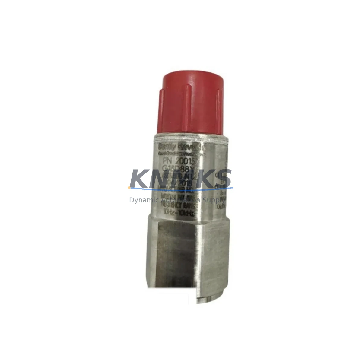
Bently Nevada 200150-13-05 Migration-Ready Accelerometer for Legacy Control Systems
The Bently Nevada 200150-13-05 is a migration-ready vibration accelerometer engineered for direct replacement within Trendmaster 2000 and Trendmaster Pro condition monitoring platforms. As legacy Bently Nevada monitoring infrastructure reaches end-of-support and spare parts availability tightens, maintenance engineers and reliability teams face increasing pressure to source tested, wiring-compatible replacements that can be installed without reprogramming the host system or modifying existing terminal blocks. The 200150-13-05 addresses this challenge with a drop-in mechanical and electrical profile that preserves the original signal chain, allowing facilities to extend the operational life of their existing monitoring architecture while deferring a full platform migration.
This accelerometer is designed for continuous vibration measurement on rotating machinery including turbines, compressors, pumps, and motors. It outputs a standard IEPE (Integrated Electronics Piezo-Electric) signal compatible with the Trendmaster 2000 Dynamic Measurement Module (DMM) and the Trendmaster Pro I/O modules. When replacing a failed or degraded 200150-13-05 in the field, engineers should verify the existing cable connector type, confirm the bias voltage supply from the connected DMM channel, and check that the sensitivity specification (typically 100 mV/g) matches the channel configuration stored in the System 1 software database. No recalibration of the monitoring channel is required when the replacement unit matches the original sensitivity rating.
For facilities running mixed Bently Nevada hardware generations, the 200150-13-05 is frequently deployed alongside the 3500/42M Proximitor/Seismic Monitor and the 3500/45 Position Monitor, which handle complementary measurement types within the same control cabinet. When planning a retrofit, it is important to confirm that the Trendmaster 2000 rack backplane has available channel slots and that the Dynamic Measurement Module firmware version supports the sensor’s output impedance. In installations where the original wiring harness has been modified or extended, signal integrity should be validated with a loop resistance check before commissioning the replacement unit.
Migration Compatibility Table
| Parameter | Detail |
|---|---|
| SKU / Part Number | 200150-13-05 |
| Brand | Bently Nevada |
| Compatible Platform | Trendmaster 2000, Trendmaster Pro |
| Sensor Type | IEPE Vibration Accelerometer |
| Output Sensitivity | 100 mV/g (nominal) |
| Connector Interface | 2-pin MIL-C-5015 style (verify existing cable) |
| Mounting | Stud mount, 1/4-28 UNF thread (confirm existing pad) |
| Signal Compatibility | IEPE / ICP — compatible with Trendmaster DMM channels |
| Communication Protocol | Analog signal to Trendmaster I/O; System 1 software integration |
| Replacement Scope | Direct drop-in for failed or end-of-life 200150-13-05 units |
| Firmware Dependency | No firmware update required on host DMM for like-for-like swap |
| Installation Space | Same physical envelope as original; confirm mounting pad clearance |
| Commissioning Check | Bias voltage, loop resistance, sensitivity match in System 1 database |
| Support terms | 12 Months from shipment date |
| Origin | China (Xiamen warehouse stock) |
Retrofit Planning for Existing Automation Systems
A successful retrofit of the 200150-13-05 within a Trendmaster 2000 or Trendmaster Pro installation requires a structured pre-replacement audit. Begin by documenting the existing channel assignment in the System 1 condition monitoring software, noting the machine tag, measurement point label, alarm setpoints, and the sensitivity value stored for the affected channel. This information must be preserved and verified against the replacement unit before the channel is returned to service.
In the same control cabinet, the Trendmaster 2000 rack typically houses a Power Supply Module alongside the Dynamic Measurement Modules. Before removing the failed accelerometer, confirm that the power supply output voltage is within specification, as an out-of-tolerance supply can damage a new sensor during commissioning. If the power supply is also approaching end-of-life, it is advisable to replace it concurrently to avoid a repeat outage. Similarly, if the installation includes a Trendmaster 2000 Communications Module for Modbus or OPC connectivity to the plant DCS, verify that the communications link remains active throughout the sensor swap to avoid triggering spurious alarms at the control room level.
For facilities that are simultaneously upgrading from Trendmaster 2000 to the Bently Nevada 3500 Series platform, the 200150-13-05 accelerometer can continue to serve as the field sensor, connected to a 3500/42M Proximitor/Seismic Monitor via an appropriate signal conditioning adapter. This approach allows the field wiring and sensor mounting to remain unchanged while the rack-level hardware is modernized. In such hybrid configurations, the 3500 rack’s I/O module addressing must be configured to match the machine database in System 1, and the HMI display faceplates should be updated to reflect the new channel source. A Bently Nevada System 1 Evolution software license may be required to support the expanded channel count after the rack upgrade.
Where the existing cable run between the sensor and the rack exceeds the manufacturer’s recommended length, a signal isolator or in-line signal conditioner may be required to maintain signal fidelity. This is particularly relevant in high-EMI environments such as motor control centers or variable frequency drive (VFD) enclosures. In these cases, a dedicated shielded cable with a drain wire terminated at a single grounding point is essential to prevent ground loop interference from corrupting the vibration signal.
Downtime Control During System Migration
Minimizing unplanned downtime during a sensor replacement on a critical rotating machine requires careful sequencing of the swap procedure. Where the process permits, the replacement should be scheduled during a planned maintenance window rather than performed as an emergency repair, as a rushed installation increases the risk of incorrect torque on the mounting stud, damaged connector pins, or an unverified sensitivity setting in the monitoring software.
Before removing the 200150-13-05 from service, place the affected monitoring channel in bypass mode within the System 1 software to prevent a spurious trip signal from reaching the DCS or safety instrumented system (SIS). Document the bypass action in the plant maintenance management system (CMMS) and set a time limit for the bypass to ensure it is not left in place indefinitely. If the machine cannot be taken offline, coordinate with the control room operator to confirm that the remaining active channels provide sufficient coverage to detect a developing fault during the bypass period.
Once the replacement sensor is installed and the connector is secured, restore the channel from bypass and observe the live vibration reading in System 1 for a minimum of 15 minutes before confirming the repair is complete. Compare the baseline vibration amplitude and frequency spectrum against the historical trend data stored in the System 1 database to confirm that the new sensor is reading within the expected range. Any significant deviation from the historical baseline should be investigated before the bypass is cleared and the channel is returned to full protective service. This final verification step is the most effective way to catch installation errors — such as a loose mounting stud or a pinched cable — before they result in a missed alarm or a false trip.
Retrofit Support FAQ
Q1: Is the 200150-13-05 a direct replacement for the original Bently Nevada part, or does it require reconfiguration in System 1?
The 200150-13-05 is a direct like-for-like replacement. Provided the replacement unit matches the original sensitivity specification (100 mV/g), no reconfiguration of the System 1 channel database is required. The machine tag, alarm setpoints, and measurement point settings remain unchanged. A post-installation verification of the live reading against the historical baseline is recommended before returning the channel to protective service.
Q2: What wiring checks should be performed before installing the replacement accelerometer?
Verify the connector type and pin assignment against the existing cable harness. Check the cable shield continuity and confirm the drain wire is terminated at a single grounding point. Measure the loop resistance of the cable run and confirm it is within the DMM channel’s specified input impedance range. Inspect the connector body for corrosion or mechanical damage before mating with the new sensor.
Q3: Has the unit been tested before shipment, and what does the support terms confirmed by quotation cover?
Yes. Each 200150-13-05 unit is function-tested prior to shipment to verify output sensitivity, bias voltage response, and connector integrity. The support terms confirmed by quotation cover manufacturing defects and functional failures under normal operating conditions from the date of shipment. It does not cover damage resulting from incorrect installation, overvoltage, mechanical impact, or operation outside the specified temperature and vibration range.
Q4: Is stock available for immediate shipment, and what are the lead times for larger quantities?
Stock is maintained in our Xiamen warehouse for immediate dispatch. Standard orders ship within 1–3 business days. For blanket orders or larger quantities required for a planned maintenance program, please contact our sales team to confirm availability and arrange a reserved stock allocation. Early engagement is recommended for critical spares programs given the limited availability of legacy Bently Nevada components on the open market.
© 2026 KNMKS. All rights reserved.
Original Source: https://knmks.com
Contact: admin@knmks.com | +86 18359268345
Product Identification
- Brand / Ecosystem
-
Bently Nevada
Bently Nevada - Model / Series
- 200150-13-05
- Product Family
- Other Components
- Availability Status
- Available on request after model and quantity confirmation
- Inquiry Type
- B2B RFQ, replacement inquiry and project spare-part request
- Pre-Quote Check
- Exact SKU, brand, series, quantity, nameplate photos and destination country are checked before quotation
System Path
Where this product fits in the KNMKS automation structure.
Specification & Inquiry Focus
- Component range
- Breakers, terminals and cabinet accessories
- Common needs
- Model, photo and installation requirement
- Project support
- Maintenance and mixed spare-part inquiry
Buyer Confirmation
Information KNMKS checks before replying.
- Exact model
- 200150-13-05
- Brand / ecosystem
- Bently Nevada
- Product family
- Other Components
- Application note
- Replacement, maintenance, project build or spare-part list
- Useful photos
- Nameplate, installed unit, cabinet layout or connector side
- Delivery details
- Quantity, destination country and target schedule
Document Support
Files and notes can be confirmed during quotation.
- Product photos or nameplate confirmation when available
- Packing and delivery notes before quotation confirmation
- Support scope and delivery terms confirmed per inquiry
- Export document coordination for qualified B2B requests
Inquiry Support
- Mixed automation spare parts inquiry
- Cabinet component and accessory support
- Model identification from photos or labels
What to Send Us
- Brand and exact model number: Bently Nevada 200150-13-05
- Quantity and required delivery time
- Application, replacement requirement or nameplate photo
- Destination country and shipping preference
RFQ Preparation
This is a product inquiry page built for RFQ communication.
Fast Model Check
Send this model to KNMKS for confirmation.
Include quantity, destination country and photos if this is a maintenance replacement. The inquiry will be saved with a reference number after submission.
Brand & Compatibility Note
KNMKS displays automation product information for well-known industrial brand ecosystems and compatible replacement references. Brand names are used for product identification and compatibility reference only; final availability and commercial terms are confirmed per quotation.
 Manufacturing
 Machine Tools
 Packaging
 Energy & Power
 PLCs & Controllers
 HMI & Displays
 Servo Systems
 Variable Frequency Drives