
Overview
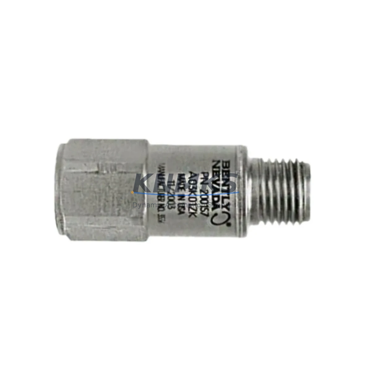
Bently Nevada 200150-10-05 Migration-Ready Accelerometer for Legacy Control Systems
The Bently Nevada 200150-10-05 is a migration-ready accelerometer engineered for seamless integration into legacy Trendmaster 2000 and Trendmaster Pro continuous monitoring systems. As rotating machinery protection programs face increasing pressure from discontinued spare parts and aging sensor infrastructure, the 200150-10-05 provides a verified drop-in replacement path that preserves existing wiring, signal conditioning, and alarm setpoint configurations without requiring a full system overhaul.
Designed for industrial environments where uptime is non-negotiable, this accelerometer delivers reliable vibration measurement across a broad frequency range, making it suitable for turbines, compressors, pumps, motors, and gearboxes operating under continuous monitoring protocols. Its compatibility with the Trendmaster I/O module architecture means that field engineers can execute a like-for-like swap with minimal reconfiguration of the host monitoring system.
When planning a retrofit involving the 200150-10-05, engineers must verify several critical parameters before committing to installation. Power supply compatibility with the Trendmaster dynamic pressure input card is the first checkpoint — confirm that the existing 24 VDC loop supply is within tolerance and that the cable run length does not introduce excessive voltage drop that would affect sensor bias output. Terminal block wiring should be documented prior to removal of the legacy sensor, as the signal, power, and shield connections must be replicated exactly to maintain measurement integrity.
Backplane interface compatibility is equally important. In systems where the 200150-10-05 feeds into a Trendmaster 6800 series rack, the slot addressing and channel mapping configured in the System 1 software must be preserved. Any change to the physical channel assignment will require a corresponding update in the System 1 database, including alarm limits, transducer scale factors, and engineering unit conversions. Firmware version alignment between the I/O module and the System 1 host should be confirmed before commissioning — mismatched firmware can cause communication dropouts or incorrect full-scale readings.
For plants running parallel migration programs, the 200150-10-05 is frequently deployed alongside the Bently Nevada 330180 proximity probe system, where accelerometers handle high-frequency structural vibration while proximity probes manage shaft relative displacement. In combined upgrade projects, the 3500/42M vibration monitor module is often introduced to consolidate both measurement types into a single rack slot, reducing panel space requirements and simplifying the HMI tag structure in the DCS. Engineers should confirm that the existing Bently Nevada 3500 rack has sufficient available slots and that the backplane communication bus is not operating at capacity before adding new modules.
HMI screen updates are a frequently underestimated step in accelerometer migration projects. When the 200150-10-05 replaces a sensor with a different sensitivity rating (mV/g), the engineering unit scaling in the operator display must be recalculated to prevent false alarm conditions. Coordinate with the control room team to freeze alarm outputs during the commissioning window and restore them only after a full vibration baseline has been established at normal operating speed.
Communication link integrity between the Trendmaster rack and the plant DCS — typically via Modbus RTU or the Bently Nevada proprietary TDI protocol — should be validated using a loop test before the unit is returned to service. Signal isolation between the accelerometer cable shield and the instrument earth ground must also be verified to prevent ground loop interference, which is a common source of elevated noise floors in legacy cable trays shared with power conductors.
Installation space confirmation is straightforward for most Trendmaster enclosures, as the 200150-10-05 uses a standard M8 mounting thread and a compact cylindrical housing. However, in confined machinery skids where cable bend radius is restricted, the connector orientation should be checked against the existing cable routing before final torque is applied to the mounting stud.
Migration Compatibility Table
| Parameter | Details |
|---|---|
| SKU / Part Number | 200150-10-05 |
| Brand | Bently Nevada |
| Series | Trendmaster 2000 / Trendmaster Pro |
| Product Type | Industrial Accelerometer (Vibration Sensor) |
| Mounting Interface | M8 threaded stud, standard Trendmaster mechanical footprint |
| Signal Output | IEPE / ICP® compatible, mV/g sensitivity |
| Power Supply | 24 VDC loop-powered via Trendmaster dynamic pressure input card |
| Compatible Racks | Trendmaster 6800 series, Bently Nevada 3500 series (with appropriate I/O module) |
| Communication Protocol | Modbus RTU, Bently Nevada TDI protocol |
| Host Software | System 1 (v5.x and above recommended) |
| Legacy Replacement Target | Discontinued Trendmaster accelerometer variants; aging sensor infrastructure |
| Commissioning Requirement | Firmware version check, channel address verification, alarm setpoint re-validation |
| Support terms | 12 months from date of shipment |
| Origin | USA |
Retrofit Planning for Existing Automation Systems
A successful retrofit centered on the 200150-10-05 requires a structured bill-of-materials review that extends beyond the sensor itself. In most Trendmaster-based monitoring architectures, the accelerometer is one node in a broader signal chain that includes the Trendmaster dynamic pressure input module, the 3500/42M vibration monitor, the Bently Nevada 3500/15 power supply module, and the System 1 data acquisition server. Each of these components must be assessed for compatibility before the replacement sensor is installed.
Terminal block wiring documentation is the foundation of any retrofit plan. Before removing the legacy accelerometer, photograph or sketch the existing terminal assignments, noting the signal conductor color, shield termination point, and any ferrite bead or in-line filter installed on the cable. This documentation will be essential if the replacement sensor exhibits unexpected noise during initial commissioning.
For plants where the Trendmaster rack is approaching end-of-support, the 200150-10-05 retrofit is often the first step in a phased migration toward the Bently Nevada 3500 platform. In this scenario, the accelerometer replacement is executed first to restore measurement confidence, followed by a planned rack migration during the next scheduled outage. The Bently Nevada 3500/22M transient data interface module is frequently specified in these phased programs to enable waveform capture during the transition period, providing baseline vibration signatures that can be compared before and after the full rack migration.
Signal isolators are sometimes required when the 200150-10-05 is installed in a cable tray environment with high electromagnetic interference from variable frequency drives or large motor starters. A DIN-rail mounted signal conditioner with galvanic isolation can be inserted between the sensor output and the Trendmaster input card without affecting the measurement chain, provided the isolator bandwidth is sufficient for the frequency range of interest.
Programming cable availability should be confirmed before the commissioning team arrives on site. System 1 configuration changes require a direct Ethernet connection to the Trendmaster rack processor, and the appropriate Bently Nevada configuration software license must be active on the engineering workstation. Scheduling the firmware verification and channel address confirmation as a pre-outage desktop exercise will reduce the time the unit spends offline during the physical swap.
Downtime Control During System Migration
Minimizing downtime during a 200150-10-05 replacement requires a pre-engineered swap procedure that has been reviewed and approved by the operations team before the maintenance window opens. The procedure should include a step-by-step sequence for inhibiting the vibration alarm in the DCS, isolating the sensor loop, removing the legacy accelerometer, installing the replacement unit, restoring the loop, and re-enabling the alarm — with a defined hold point at each stage for verification.
Preserving the original program logic in System 1 is critical. Before any physical work begins, export the current System 1 database to a backup file and store it on a network drive accessible to both the maintenance team and the control room. This backup ensures that if the commissioning process reveals an unexpected compatibility issue, the system can be restored to its pre-maintenance state without loss of alarm configuration or historical trend data.
Field control continuity during the swap can be maintained by temporarily routing the vibration monitoring function to a portable data collector if the plant safety case permits. This approach allows the operations team to maintain awareness of machine condition during the brief period when the permanent sensor is disconnected, reducing the risk of an undetected vibration event during the maintenance window.
Post-installation, a full-speed run-up vibration baseline should be recorded and compared against the pre-maintenance trend data stored in System 1. Any deviation greater than the established alarm threshold should be investigated before the unit is returned to normal operation. This final verification step is the most effective risk control in the retrofit process and should not be abbreviated due to schedule pressure.
Retrofit Support FAQ
Q: Is the 200150-10-05 a direct drop-in replacement for the original Trendmaster accelerometer?
A: Yes, the 200150-10-05 is designed as a migration-ready replacement for legacy Trendmaster accelerometer variants. The mechanical mounting interface, connector type, and signal output characteristics are compatible with existing Trendmaster dynamic pressure input cards. Minor sensitivity differences between the original and replacement sensor may require a scale factor update in System 1, which can be performed without a system restart.
Q: What commissioning steps are required after installation?
A: After physical installation, verify the sensor bias voltage at the Trendmaster input card terminal to confirm the sensor is powered and operational. Update the transducer scale factor in System 1 if the sensitivity rating differs from the original sensor. Perform a bump test or use a calibrated shaker to confirm the measurement chain is responding correctly before re-enabling vibration alarms.
Q: How is the unit tested before shipment?
A: Each 200150-10-05 unit undergoes functional testing prior to shipment, including bias output verification and sensitivity confirmation. A test report is available upon request. Units are shipped in anti-static packaging with protective end caps to prevent connector damage during transit.
Q: What support terms coverage is provided?
A: All units are covered by a support terms confirmed by quotation from the date of shipment. The support terms covers manufacturing defects and functional failures under normal operating conditions. Support requests are supported by our technical team, and replacement units can be dispatched from regional stock to minimize lead time impact on your maintenance program.
© 2026 KNMKS. All rights reserved.
Original Source: https://knmks.com
Contact: admin@knmks.com | +86 18359268345
Product Identification
- Brand / Ecosystem
-
Bently Nevada
Bently Nevada - Model / Series
- 200150-10-05
- Product Family
- Sensors
- Availability Status
- Available on request after model and quantity confirmation
- Inquiry Type
- B2B RFQ, replacement inquiry and project spare-part request
- Pre-Quote Check
- Exact SKU, brand, series, quantity, nameplate photos and destination country are checked before quotation
System Path
Where this product fits in the KNMKS automation structure.
Specification & Inquiry Focus
- Sensor range
- Photoelectric, proximity and process sensors
- Common needs
- Output type, distance and connector
- Project support
- Machine detection and replacement inquiry
Buyer Confirmation
Information KNMKS checks before replying.
- Exact model
- 200150-10-05
- Brand / ecosystem
- Bently Nevada
- Product family
- Sensors
- Application note
- Replacement, maintenance, project build or spare-part list
- Useful photos
- Nameplate, installed unit, cabinet layout or connector side
- Delivery details
- Quantity, destination country and target schedule
Document Support
Files and notes can be confirmed during quotation.
- Product photos or nameplate confirmation when available
- Packing and delivery notes before quotation confirmation
- Support scope and delivery terms confirmed per inquiry
- Export document coordination for qualified B2B requests
Inquiry Support
- NPN/PNP, analog and digital output checking
- Connector and cable compatibility review
- Fast inquiry support for maintenance teams
What to Send Us
- Brand and exact model number: Bently Nevada 200150-10-05
- Quantity and required delivery time
- Application, replacement requirement or nameplate photo
- Destination country and shipping preference
RFQ Preparation
This is a product inquiry page built for RFQ communication.
Fast Model Check
Send this model to KNMKS for confirmation.
Include quantity, destination country and photos if this is a maintenance replacement. The inquiry will be saved with a reference number after submission.
Brand & Compatibility Note
KNMKS displays automation product information for well-known industrial brand ecosystems and compatible replacement references. Brand names are used for product identification and compatibility reference only; final availability and commercial terms are confirmed per quotation.
 Manufacturing
 Machine Tools
 Packaging
 Energy & Power

 PLCs & Controllers
 HMI & Displays
 Servo Systems
 Variable Frequency Drives