
Overview
Bently Nevada 190501-24-99-CN Migration-Ready Velocity Transducer: Legacy System Retrofit and Compatibility Upgrade
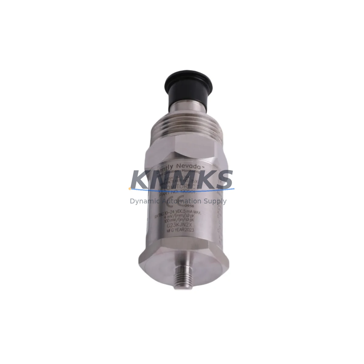
The Bently Nevada 190501-24-99-CN Velomitor CT is a piezoelectric velocity transducer engineered for direct drop-in replacement of discontinued and end-of-life velocity sensors across Bently Nevada 3300 Series and 3500 Series machinery protection platforms. Designed to meet the demanding requirements of rotating machinery monitoring in petrochemical, power generation, compressor, and turbine applications, this unit delivers a broadband frequency response of 2 Hz to 1,000 Hz with a sensitivity of 100 mV/in/s (4 mV/mm/s), making it fully compatible with existing signal conditioning infrastructure without requiring recalibration of the monitoring rack.
For maintenance engineers managing aging DCS and machinery protection systems, the 190501-24-99-CN addresses one of the most common retrofit challenges: replacing a velocity sensor without triggering a cascade of downstream configuration changes. The unit’s output impedance, connector pinout, and cable interface are backward-compatible with the standard Bently Nevada 9-pin MIL-C-5015 connector used across the 3300 XL 11 mm Proximity Transducer System and the 3500/42M Proximitor/Seismic Monitor module. This means field technicians can complete a sensor swap during a planned maintenance window without modifying the existing Proximitor signal conditioner wiring or the 3500 rack I/O termination block assignments.
Migration Compatibility Table
| Parameter | 190501-24-99-CN (This Unit) | Legacy / Replaced Models | Retrofit Notes |
|---|---|---|---|
| Sensitivity | 100 mV/in/s ± 5% | 190501-01, 190501-02 series | No rack rescaling required; direct substitution |
| Frequency Response | 2 Hz – 1,000 Hz (±3 dB) | Same range as 3300 XL velocity inputs | Compatible with 3500/42M seismic channel configuration |
| Connector Interface | MIL-C-5015 9-pin | Standard BN field wiring connector | Reuse existing armored cable; no re-termination needed |
| Mounting | 1/4-28 UNF stud mount | Same as 190501 series predecessors | No bracket modification; confirm torque spec (15 in-lb) |
| Operating Temperature | -40°C to +121°C | Standard industrial range | Suitable for hot-section turbine bearing housings |
| Supply Voltage | 18–30 VDC (loop-powered) | Matches 3500 rack power supply output | Verify 3500/15 Power Supply module output under full load |
| Communication / Signal | Analog voltage output (passive) | Direct to 3500/42M or 3300 XL monitor | No protocol migration required; analog signal path preserved |
| Replacement Compatibility | 3300 XL, 3500/42M, 3500/45 | 190501-01, -02, -03, -24 variants | Confirm suffix (-99-CN) matches regional certification requirement |
| Commissioning | Zero-offset verification at rack | Standard BN commissioning procedure | Use Bently Nevada 3500 Rack Configuration Software for channel validation |
| Support terms | support terms confirmed by quotation — covers manufacturing defects, signal drift, and connector integrity from date of shipment | ||
Retrofit Planning for Existing Automation Systems
A successful retrofit of the 190501-24-99-CN into an operating machinery protection system requires a structured pre-installation review. Before removing the legacy sensor, the maintenance team should document the current vibration baseline readings from the 3500/42M Proximitor/Seismic Monitor to establish a pre-swap reference. This baseline is critical for post-installation acceptance testing and for validating that the new transducer is reading within the expected amplitude and phase envelope for the monitored machine train.
The 3500 rack architecture typically houses the 3500/42M seismic monitor alongside the 3500/20 Rack Interface Module, the 3500/15 Power Supply, and — in turbine applications — the 3500/45 Position Monitor for axial thrust measurement. When planning the sensor replacement, confirm that the 3500/15 Power Supply module is delivering stable 24 VDC to the transducer loop under the full channel load of the populated rack. A marginal power supply that is already near its rated output capacity may exhibit voltage sag when the new transducer is connected, which can produce false alert or danger trips during the commissioning phase.
For installations where the 190501-24-99-CN is replacing a sensor on a machine that also uses the Bently Nevada 3300 XL 8 mm Proximity Transducer System for radial shaft vibration, the field team should verify that the proximity transducer driver and the velocity transducer signal are routed to separate monitor channels and that the I/O termination block assignments in the 3500 rack have not been inadvertently shared. Cross-channel wiring errors are a common source of nuisance trips during sensor replacement work and are best caught during a bench-level continuity check before the rack is returned to service.
In applications where the control system integrates machinery protection data into a DCS — such as a Honeywell Experion PKS or an Emerson DeltaV system — the analog output from the 3500/42M monitor feeds into the DCS I/O card via a 4–20 mA or 0–10 V signal. After replacing the velocity transducer, the DCS operator should verify that the process variable displayed on the HMI faceplate for the affected machine train matches the local rack display. Discrepancies between the rack reading and the DCS display typically indicate a scaling mismatch in the DCS I/O configuration rather than a transducer fault, and can be resolved by reviewing the engineering unit conversion in the DCS controller tag database without requiring a second sensor replacement.
Where the installation involves a signal isolator or signal conditioner between the 3500 rack output and the DCS I/O card — such as a Phoenix Contact MACX or a Pepperl+Fuchs KFD2-series isolator — the isolator’s input range should be confirmed against the 3500/42M output specification before the new transducer is commissioned. A mismatch in isolator input range is a low-visibility failure mode that can cause the DCS to display a clipped or saturated reading even when the transducer and rack are functioning correctly.
Downtime Control During System Migration
Minimizing unplanned downtime during a velocity transducer replacement on a live machine train requires a disciplined sequence of pre-work, execution, and verification steps. The recommended approach is to perform the sensor swap during a scheduled maintenance window when the machine is in a controlled shutdown state, with the 3500 rack placed in bypass mode for the affected channel to prevent spurious trips from propagating to the ESD system during the physical swap.
Before entering bypass, the control room operator should confirm with the field team that the machine is at rest and that the process is in a safe hold state. The 3500 Rack Configuration Software should be used to place the specific monitor channel into bypass, and the bypass action should be logged in the plant maintenance management system with a time stamp and the name of the authorizing engineer. This audit trail is required by most plant safety management systems and protects the maintenance team in the event of a post-maintenance incident review.
The physical replacement of the 190501-24-99-CN takes approximately 15 to 30 minutes for an experienced field technician, assuming the existing armored cable is in good condition and the connector is not corroded. If the connector shows signs of moisture ingress or pin corrosion — a common finding on sensors that have been in service for more than five years in outdoor or high-humidity environments — the cable end should be re-terminated before the new sensor is installed. Attempting to reuse a corroded connector is the single most common cause of intermittent signal faults in the weeks following a sensor replacement.
After the new transducer is installed and the connector is secured, the field technician should perform a static output check using a portable millivolt meter before the rack channel is taken out of bypass. The 190501-24-99-CN should produce a DC bias voltage of approximately 8–12 VDC at the monitor input terminals when the machine is at rest, consistent with the Velomitor CT specification. A reading outside this range indicates a wiring fault or a connector pin assignment error and should be resolved before the channel is returned to active monitoring. Once the static check is confirmed, the bypass is removed, the machine is restarted, and the post-installation vibration baseline is compared against the pre-swap reference to confirm that the replacement has been completed successfully.
Retrofit Support FAQ
Q1: Is the 190501-24-99-CN a direct drop-in replacement for the 190501-01 and 190501-02?
Yes. The 190501-24-99-CN shares the same sensitivity (100 mV/in/s), connector interface (MIL-C-5015 9-pin), mounting thread (1/4-28 UNF), and frequency response as the earlier -01 and -02 suffix variants. The -24 suffix denotes the cable length (24 inches), and the -99-CN suffix indicates the regional certification variant. No changes to the 3500 rack channel configuration or the Proximitor signal conditioner are required for a direct substitution.
Q2: What commissioning steps are required after installation?
After physical installation, perform a static DC bias check at the monitor input terminals (expected: 8–12 VDC at rest). Then use the Bently Nevada 3500 Rack Configuration Software to run a channel self-test and verify that the OK relay is energized and the vibration reading is within the expected baseline range for the machine at rest. Compare the post-installation reading against the pre-swap baseline documented before the sensor was removed. No firmware update to the 3500 rack is required for this replacement.
Q3: Can this unit be used with a Honeywell or Emerson DCS without additional signal conditioning?
The 190501-24-99-CN outputs a passive analog voltage signal that is processed by the 3500/42M monitor, which in turn provides a 4–20 mA or 0–10 V output to the DCS I/O card. The transducer itself does not connect directly to the DCS. If a signal isolator such as a Phoenix Contact MACX or a Pepperl+Fuchs KFD2-series unit is installed in the signal path, verify that its input range matches the 3500/42M output specification before commissioning.
Q4: What does the support terms confirmed by quotation cover, and what is the lead time for in-stock units?
The support terms confirmed by quotation cover manufacturing defects, signal sensitivity drift beyond the ±5% specification, and connector integrity failures from the date of shipment. Units are tested prior to dispatch and shipped with a test report. In-stock units are available for same-week dispatch. For bulk orders or blanket-stock programs supporting multi-site maintenance contracts, contact the sales team to discuss allocation and lead-time commitments.
© 2026 KNMKS. All rights reserved.
Original Source: https://knmks.com
Contact: admin@knmks.com | +86 18359268345
Product Identification
- Brand / Ecosystem
-
Bently Nevada
Bently Nevada - Model / Series
-
190501-24-99-CN
3500 Series - Product Family
- Sensors
- Availability Status
- Available on request after model and quantity confirmation
- Inquiry Type
- B2B RFQ, replacement inquiry and project spare-part request
- Pre-Quote Check
- Exact SKU, brand, series, quantity, nameplate photos and destination country are checked before quotation
System Path
Where this product fits in the KNMKS automation structure.
Specification & Inquiry Focus
- Sensor range
- Photoelectric, proximity and process sensors
- Common needs
- Output type, distance and connector
- Project support
- Machine detection and replacement inquiry
Buyer Confirmation
Information KNMKS checks before replying.
- Exact model
- 190501-24-99-CN
- Brand / ecosystem
- Bently Nevada
- Product family
- Sensors
- Application note
- Replacement, maintenance, project build or spare-part list
- Useful photos
- Nameplate, installed unit, cabinet layout or connector side
- Delivery details
- Quantity, destination country and target schedule
Document Support
Files and notes can be confirmed during quotation.
- Product photos or nameplate confirmation when available
- Packing and delivery notes before quotation confirmation
- Support scope and delivery terms confirmed per inquiry
- Export document coordination for qualified B2B requests
Inquiry Support
- NPN/PNP, analog and digital output checking
- Connector and cable compatibility review
- Fast inquiry support for maintenance teams
What to Send Us
- Brand and exact model number: Bently Nevada 190501-24-99-CN
- Quantity and required delivery time
- Application, replacement requirement or nameplate photo
- Destination country and shipping preference
RFQ Preparation
This is a product inquiry page built for RFQ communication.
Fast Model Check
Send this model to KNMKS for confirmation.
Include quantity, destination country and photos if this is a maintenance replacement. The inquiry will be saved with a reference number after submission.
Brand & Compatibility Note
KNMKS displays automation product information for well-known industrial brand ecosystems and compatible replacement references. Brand names are used for product identification and compatibility reference only; final availability and commercial terms are confirmed per quotation.
 Manufacturing
 Machine Tools
 Packaging
 Energy & Power

 PLCs & Controllers
 HMI & Displays
 Servo Systems
 Variable Frequency Drives