
Overview
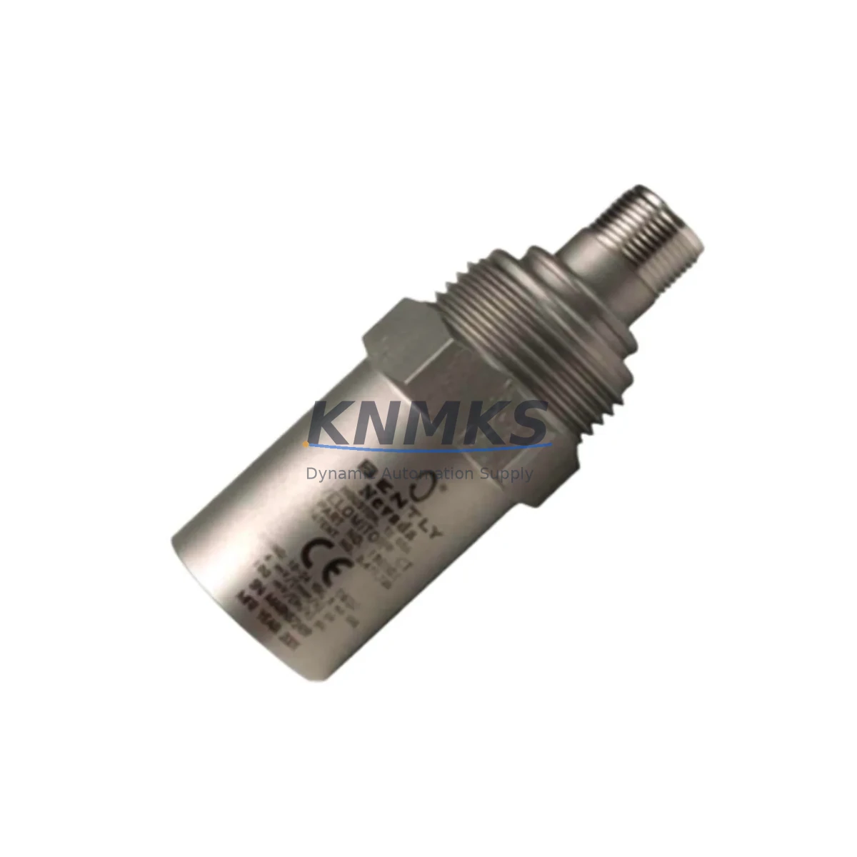
Bently Nevada 190501-22-00-01 Maintenance-Proven Spare Part for Factory Uptime
The Bently Nevada 190501-22-00-01 Velomitor CT is a high-performance velocity transducer engineered for continuous vibration monitoring in rotating machinery applications across oil & gas, power generation, petrochemical, and heavy industrial environments. As a direct original spare, this unit delivers the measurement accuracy and signal integrity that maintenance engineers depend on to sustain plant uptime and prevent unplanned shutdowns. Whether you are replacing a failed sensor during an emergency outage or building a proactive spare parts inventory ahead of a scheduled turnaround, the 190501-22-00-01 is a field-proven component that integrates seamlessly into existing Bently Nevada 3500 Series machinery protection systems without requiring reconfiguration or recalibration of the monitoring rack.
Procurement engineers sourcing this transducer for critical rotating assets — including steam turbines, gas compressors, pumps, and gearboxes — can rely on KNMKS for tested, support terms-backed stock with fast global dispatch. Every unit shipped undergoes pre-delivery functional verification to confirm output sensitivity, frequency response, and connector integrity before leaving our warehouse. A support terms confirmed by quotation cover all units against manufacturing defects and performance deviation from published specifications.
Spare Maintenance Table
| Part Number | 190501-22-00-01 |
| Brand | Bently Nevada |
| Series | Velomitor CT |
| Product Type | Velocity Transducer (Seismic) |
| Measurement Type | Absolute Casing Vibration Velocity |
| Output Sensitivity | 100 mV/in/s (4 mV/mm/s) |
| Frequency Range | 2 Hz – 1,000 Hz (±3 dB) |
| Operating Temperature | -40°C to +121°C (-40°F to +250°F) |
| Connector Type | 2-pin MIL-C-5015 (integral cable available) |
| Housing Material | Stainless Steel |
| Ingress Protection | IP67 |
| Compatible System | Bently Nevada 3500 Series Machinery Protection |
| Compatible Monitor Cards | 3500/42M, 3500/45, 3500/46M Vibration Monitor Modules |
| Mounting | 1/4-28 UNF threaded stud or adhesive pad |
| Origin | USA |
| Support terms | 12 Months from shipment date |
| Condition | New / Surplus New |
| Lead Time | availability confirmed by RFQ — Ships within 2 business days |
Maintenance Planning for Continuous Operation
When replacing the Bently Nevada 190501-22-00-01 Velomitor CT during a planned or emergency maintenance event, a thorough inspection of the surrounding measurement loop and protection system is essential to avoid repeat failures and ensure the replacement unit performs to specification from the moment it is commissioned.
Begin by inspecting the Bently Nevada 3500/42M or 3500/45 Vibration Monitor Module in the protection rack. A faulty or drifting monitor card can mask true vibration readings or generate nuisance trips even after a transducer replacement. Verify that the monitor’s OK relay is functioning and that channel configuration — including full-scale range, alert, and danger setpoints — matches the new transducer’s sensitivity specification.
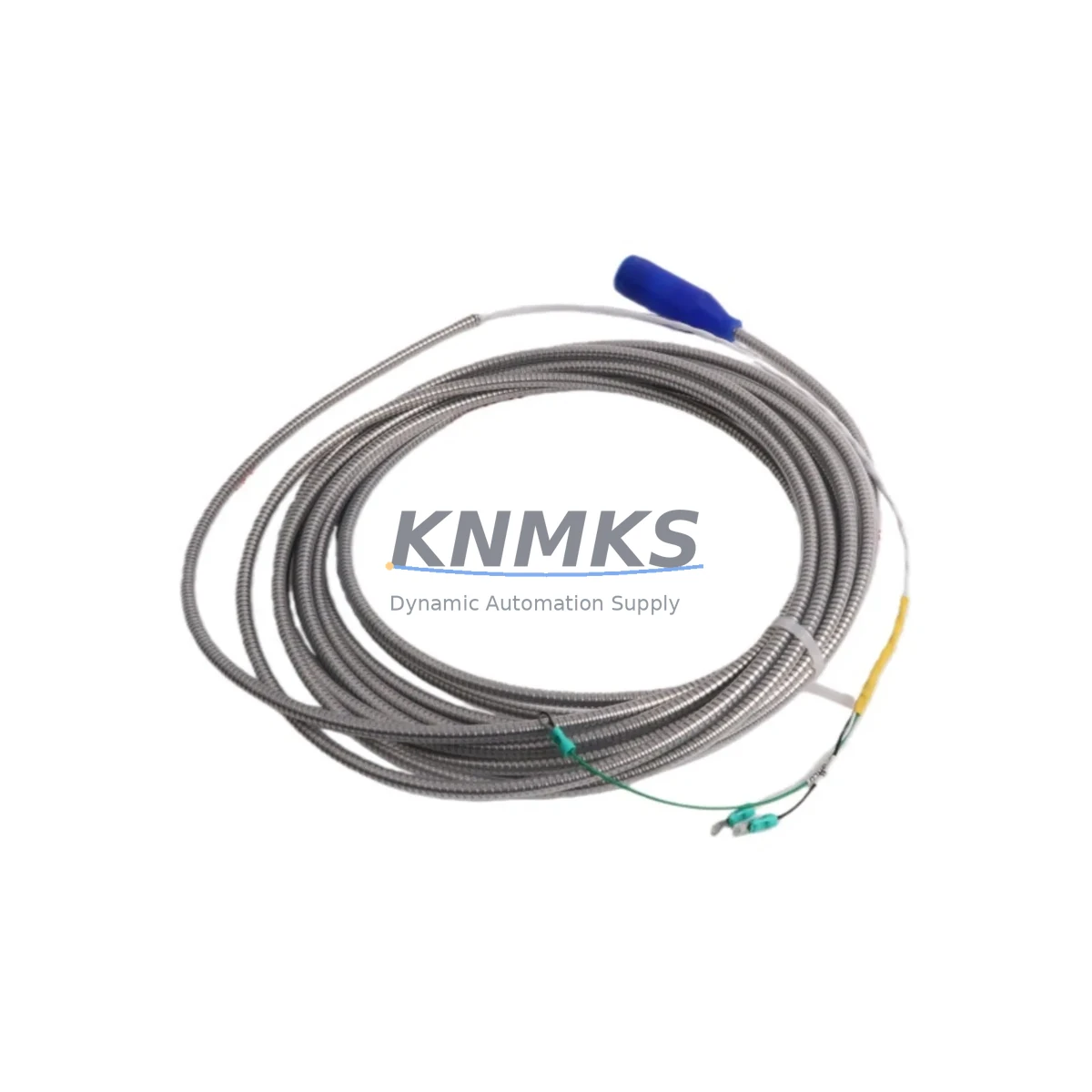
Check the interconnecting field wiring and armored cable assembly between the transducer mounting point and the junction box. Velomitor CT sensors are susceptible to ground loops and shield continuity issues that introduce noise into the velocity signal. Inspect the cable shield termination at both ends and confirm that only one end is grounded per Bently Nevada wiring guidelines.
Inspect the 3500/15 Power Supply Module or equivalent rack power supply feeding the 3500 chassis. An unstable or under-voltage power supply can cause intermittent OK status faults on velocity channels and should be verified with a calibrated DC voltmeter before the replacement transducer is declared healthy.
If the machine is also equipped with Bently Nevada 3300 XL 8mm or 3300 XL 11mm proximity probes for shaft displacement monitoring, confirm that those channels remain within gap voltage specification after any mechanical work performed during the transducer replacement outage. Displacement and velocity channels together provide a complete picture of rotor and casing dynamics.
For installations where the 3500 rack communicates with a DCS or SCADA platform via Modbus TCP or OPC-DA/UA gateway modules, verify that the communication link remains active after the maintenance window and that vibration data is being correctly received at the control room historian. A communication dropout during restart can delay the detection of post-maintenance vibration anomalies.
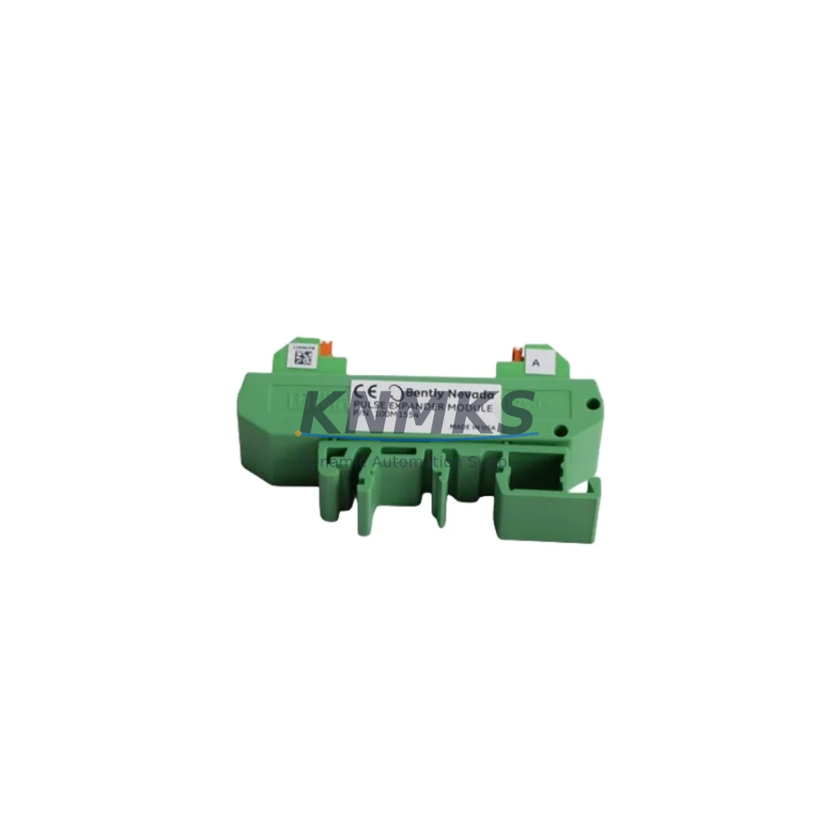
Finally, review the condition of the terminal block assemblies and DIN rail mounted signal isolators within the local junction box. Corroded terminals or degraded isolators are a common source of signal offset errors that are frequently misattributed to transducer failure. Replacing the transducer without addressing terminal integrity will result in a repeat call-out within the same maintenance cycle.
Site Replacement Workflow
Step 1 — Isolation and Permit: Obtain a valid work permit and confirm that the machinery protection system is in bypass mode for the affected channel before disconnecting the existing transducer. Do not remove the sensor while the machine is running unless the channel has been formally bypassed at the 3500 rack.
Step 2 — Physical Removal: Disconnect the field cable at the transducer connector. Remove the 190501-22-00-01 from its mounting stud or adhesive pad. Inspect the mounting surface for corrosion, thread damage, or contamination that could affect the new unit’s coupling efficiency.
Step 3 — Installation of Replacement Unit: Mount the new 190501-22-00-01 to the cleaned and prepared surface. Torque the mounting stud to the manufacturer’s specification. Reconnect the field cable, ensuring the connector is fully seated and the locking ring is engaged. Verify cable routing avoids heat sources and mechanical contact points.
Step 4 — Loop Verification: With the machine at rest, confirm the 3500 monitor channel shows an OK status and a baseline velocity reading within the expected noise floor. Use a portable vibration calibrator if available to inject a known reference signal and verify end-to-end channel accuracy before returning the machine to service.
Step 5 — Return to Service: Remove the channel bypass at the 3500 rack. Confirm that the OK relay is energized and that the channel is actively contributing to the machinery protection logic. Document the replacement in the plant CMMS with the new unit’s serial number and installation date to support future support requests and maintenance scheduling.
Spare Parts Support FAQ
Q1: Is the 190501-22-00-01 a direct drop-in replacement for older Velomitor CT variants?
Yes. The 190501-22-00-01 maintains the same mechanical envelope, connector pinout, and output sensitivity as earlier Velomitor CT configurations. It is compatible with all 3500 Series vibration monitor modules that accept a velocity transducer input without requiring firmware updates or channel reconfiguration.
Q2: What pre-shipment testing is performed on each unit?
Every 190501-22-00-01 shipped by KNMKS undergoes functional output verification, connector integrity inspection, and sensitivity confirmation against the published 100 mV/in/s specification. A test report is available upon request for critical applications requiring documented traceability.
Q3: How should I structure my spare parts inventory for Velomitor CT transducers?
For facilities operating more than four Velomitor CT channels on critical machinery, we recommend maintaining a minimum of two on-shelf spares per site. Given that Bently Nevada has transitioned some legacy Velomitor variants to limited availability, holding a buffer stock of the 190501-22-00-01 protects against lead-time risk during peak demand periods or supplier allocation constraints.
Q4: What is covered under the support terms confirmed by quotation?
The support terms confirmed by quotation cover manufacturing defects, connector failure, and performance deviation from the published sensitivity and frequency response specifications under normal operating conditions. Support requests are processed directly through KNMKS with a target response time of two business days. Physical damage resulting from incorrect installation, over-torquing, or exposure beyond the rated temperature range is excluded.
© 2026 KNMKS. All rights reserved.
Original Source: https://knmks.com
Contact: admin@knmks.com | +86 18359268345
Product Identification
- Brand / Ecosystem
-
Bently Nevada
Bently Nevada - Model / Series
- 190501-22-00-01
- Product Family
- Sensors
- Availability Status
- Available on request after model and quantity confirmation
- Inquiry Type
- B2B RFQ, replacement inquiry and project spare-part request
- Pre-Quote Check
- Exact SKU, brand, series, quantity, nameplate photos and destination country are checked before quotation
System Path
Where this product fits in the KNMKS automation structure.
Specification & Inquiry Focus
- Sensor range
- Photoelectric, proximity and process sensors
- Common needs
- Output type, distance and connector
- Project support
- Machine detection and replacement inquiry
Buyer Confirmation
Information KNMKS checks before replying.
- Exact model
- 190501-22-00-01
- Brand / ecosystem
- Bently Nevada
- Product family
- Sensors
- Application note
- Replacement, maintenance, project build or spare-part list
- Useful photos
- Nameplate, installed unit, cabinet layout or connector side
- Delivery details
- Quantity, destination country and target schedule
Document Support
Files and notes can be confirmed during quotation.
- Product photos or nameplate confirmation when available
- Packing and delivery notes before quotation confirmation
- Support scope and delivery terms confirmed per inquiry
- Export document coordination for qualified B2B requests
Inquiry Support
- NPN/PNP, analog and digital output checking
- Connector and cable compatibility review
- Fast inquiry support for maintenance teams
What to Send Us
- Brand and exact model number: Bently Nevada 190501-22-00-01
- Quantity and required delivery time
- Application, replacement requirement or nameplate photo
- Destination country and shipping preference
RFQ Preparation
This is a product inquiry page built for RFQ communication.
Fast Model Check
Send this model to KNMKS for confirmation.
Include quantity, destination country and photos if this is a maintenance replacement. The inquiry will be saved with a reference number after submission.
Brand & Compatibility Note
KNMKS displays automation product information for well-known industrial brand ecosystems and compatible replacement references. Brand names are used for product identification and compatibility reference only; final availability and commercial terms are confirmed per quotation.
 Manufacturing
 Machine Tools
 Packaging
 Energy & Power

 PLCs & Controllers
 HMI & Displays
 Servo Systems
 Variable Frequency Drives