
Overview
Bently Nevada 190501-21-99-04 Migration-Ready Seismic Velocity Transducer for Legacy Control Systems
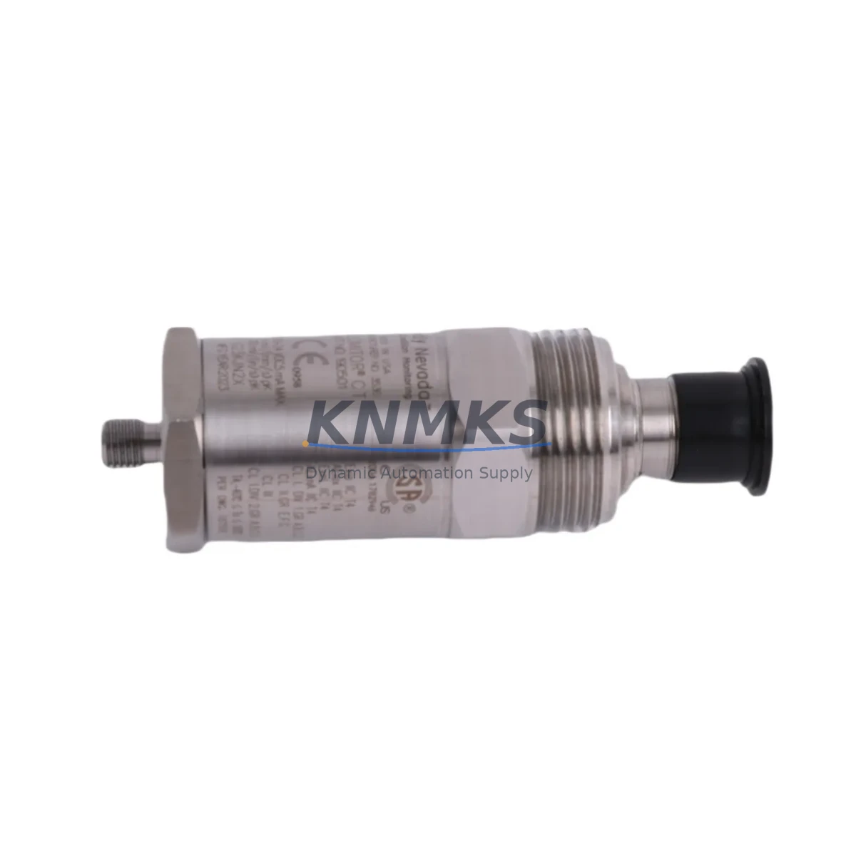
The Bently Nevada 190501-21-99-04 is a migration-ready seismic velocity transducer engineered for direct replacement of discontinued and end-of-life units within the 190501 Series platform. Designed for continuous vibration monitoring in rotating machinery protection systems, this transducer delivers reliable velocity signal output compatible with legacy Bently Nevada 3500 Series rack-based monitoring systems, as well as modern ADRE and System 1 condition monitoring platforms. For maintenance engineers managing aging DCS or machinery protection infrastructure, the 190501-21-99-04 provides a verified drop-in upgrade path that eliminates the need for full rack replacement or signal conditioning redesign.
When replacing a failed or end-of-life seismic transducer in an existing control cabinet, engineers must confirm several critical parameters before installation. Power supply compatibility — typically 24 VDC loop-powered or passive velocity output — must be verified against the existing Bently Nevada 3500/42M or 3500/45 monitor card. Terminal wiring polarity, cable shield grounding, and connector type (typically MIL-C-5015 or equivalent field-wiring termination) must match the existing field cable to avoid signal inversion or ground loop interference. Backplane slot addressing and channel assignment within the 3500 rack must be preserved to maintain alarm setpoint integrity and avoid false trips during commissioning. If the existing system uses a Bently Nevada 3500/20 rack interface module or a 3500/22M transient data interface, firmware version compatibility should be confirmed before energizing the replacement unit.
For plants running System 1 Evolution software, the transducer’s sensitivity (typically expressed in mV/mm/s or mV/in/s) must match the configured channel scaling to ensure accurate trend data continuity. Any deviation in sensitivity between the legacy unit and the 190501-21-99-04 replacement will require a recalibration step within the System 1 database — a process that should be completed during the planned outage window to avoid alarm suppression gaps.
Migration Compatibility Table
| Parameter | Legacy Unit (190501 Series) | 190501-21-99-04 Replacement | Action Required |
|---|---|---|---|
| Output Signal Type | Passive velocity (mV/mm/s) | Passive velocity (mV/mm/s) | No change required |
| Connector / Termination | MIL-C-5015 or field-wired | MIL-C-5015 compatible | Verify field cable connector type |
| Mounting Interface | Stud-mount or magnetic base | Stud-mount compatible | Confirm mounting thread spec |
| Monitor Card Compatibility | 3500/42M, 3500/45 | 3500/42M, 3500/45 compatible | No rack modification needed |
| Communication Protocol | Analog (passive velocity) | Analog (passive velocity) | No protocol migration required |
| Installation Space | Standard 190501 Series envelope | Same form factor | No mechanical modification |
| Firmware / Software | System 1 / ADRE channel config | Compatible — sensitivity recal may apply | Verify channel scaling in System 1 |
| Commissioning Focus | Alarm setpoints, trend baseline | Re-baseline after installation | Capture pre/post vibration trend |
| Support terms | — | support terms confirmed by quotation | Included — no additional cost |
Retrofit Planning for Existing Automation Systems
A successful retrofit of the 190501-21-99-04 into an operating machinery protection system requires a structured pre-outage checklist. Before the planned maintenance window, the engineering team should pull the existing channel configuration from the Bently Nevada 3500 rack — including alarm setpoints, danger levels, and OK relay logic — and archive this data in the System 1 database or a local configuration backup. This ensures that if the 3500/20 rack interface module or 3500/22M transient data interface requires a firmware update during the outage, the channel configuration can be restored without manual re-entry.
In the field cabinet, the existing signal cable from the transducer to the 3500/42M or 3500/45 monitor card should be inspected for insulation integrity and shield continuity. Cables showing degradation should be replaced with shielded twisted-pair instrumentation cable rated for the installation environment — particularly in high-temperature or high-vibration zones near turbine casings or compressor skids. If the existing cable run passes through a signal isolator or barrier (common in hazardous area installations), the isolator’s input impedance must be verified against the 190501-21-99-04 output impedance to prevent signal loading errors.
For plants that have already migrated their DCS to a modern platform — such as an Emerson DeltaV or Honeywell Experion PKS — the seismic transducer signal is typically routed through a Bently Nevada 3500 rack acting as a machinery protection gateway, with digital output (Modbus RTU or OPC-DA) feeding the DCS historian. In this architecture, the 190501-21-99-04 replacement does not require any DCS configuration change, provided the 3500 rack channel mapping and Modbus register assignments remain unchanged. However, if the plant is also upgrading the 3500 rack firmware or replacing a 3500/01 power supply module during the same outage, the sequence of operations must be carefully planned to avoid simultaneous loss of protection on multiple machinery trains.
HMI faceplate displays tied to the seismic channel — whether running on a Wonderware InTouch, FactoryTalk View, or System 1 Evolution dashboard — should be reviewed post-installation to confirm that the velocity trend tag is updating correctly and that the OK status relay is energized. Any HMI alarm suppression applied during the outage must be lifted and verified before returning the machinery to service.
Downtime Control During System Migration
Minimizing unplanned downtime during a seismic transducer replacement requires pre-staging the 190501-21-99-04 unit and all associated hardware — including replacement cable, mounting hardware, and any required signal isolators — before the outage begins. A pre-tested spare, verified against the existing channel configuration in a bench test environment, reduces the risk of discovering a compatibility issue after the machinery has been taken offline.
During the outage, the original program logic in the 3500 rack should not be modified unless a firmware update is explicitly required. Preserving the existing alarm setpoints, danger levels, and OK relay logic eliminates the risk of misconfiguration and reduces commissioning time. If the plant’s safety instrumented system (SIS) is interlocked with the machinery protection rack, the SIS bypass procedure must be activated and documented before any wiring work begins, and the bypass must be removed and verified before restart.
Post-installation, a short run-up test at reduced load — if operationally feasible — allows the engineering team to capture a baseline vibration trend on the new transducer and compare it against historical data. Any significant deviation from the pre-outage baseline should be investigated before returning to full load. This step also confirms that the 190501-21-99-04 is correctly oriented relative to the machine’s primary vibration axis, and that the mounting stud torque is within specification to avoid resonance-induced signal artifacts.
With proper pre-outage preparation, the physical replacement of a 190501 Series seismic transducer can typically be completed within a two- to four-hour maintenance window, including cable inspection, mounting, wiring verification, and System 1 channel re-baselining. All units supplied by KNMKS are pre-tested and shipped with a support terms confirmed by quotation, supporting your maintenance team’s confidence in the replacement component before it enters service.
Retrofit Support FAQ
Q1: Is the 190501-21-99-04 a direct drop-in replacement for other 190501 Series variants?
The 190501-21-99-04 is designed as a migration-ready replacement within the 190501 Series. Most variants share the same passive velocity output signal and MIL-C-5015 compatible connector, making direct substitution feasible in the majority of installations. However, engineers should confirm the specific sensitivity rating (mV/mm/s) and mounting thread specification of the unit being replaced, as sub-variants may differ. KNMKS can provide a pre-shipment datasheet for cross-reference before the order is placed.
Q2: What commissioning steps are required after installation?
After physical installation and wiring, the primary commissioning steps are: (1) verify OK relay status on the 3500/42M or 3500/45 monitor card, (2) confirm channel scaling in System 1 or ADRE matches the transducer sensitivity, (3) capture a baseline vibration trend at normal operating speed, and (4) verify that all alarm and danger setpoints are active and correctly configured. If a signal isolator is in the loop, verify output signal level at the monitor card input terminals.
Q3: Can this transducer be used with non-Bently Nevada monitoring systems?
Yes. The 190501-21-99-04 produces a standard passive velocity output signal that is compatible with most third-party vibration monitoring systems capable of accepting a velocity transducer input. Signal conditioning requirements — including input impedance and frequency response — should be verified against the target monitoring system’s specifications. KNMKS technical support can assist with compatibility assessment for specific third-party platforms.
Q4: What does the support terms confirmed by quotation cover, and what is the lead time?
All 190501-21-99-04 units supplied by KNMKS carry a support terms confirmed by quotation covering manufacturing defects and functional performance under normal operating conditions. Units are pre-tested prior to shipment. Lead time varies by stock availability — KNMKS maintains regional inventory to support urgent maintenance requirements. Contact admin@knmks.com or +86 18359268345 for current stock status and expedited shipping options.
© 2026 KNMKS. All rights reserved.
Original Source: https://knmks.com
Contact: admin@knmks.com | +86 18359268345
Product Identification
- Brand / Ecosystem
-
Bently Nevada
Bently Nevada - Model / Series
- 190501-21-99-04
- Product Family
- Sensors
- Availability Status
- Available on request after model and quantity confirmation
- Inquiry Type
- B2B RFQ, replacement inquiry and project spare-part request
- Pre-Quote Check
- Exact SKU, brand, series, quantity, nameplate photos and destination country are checked before quotation
System Path
Where this product fits in the KNMKS automation structure.
Specification & Inquiry Focus
- Sensor range
- Photoelectric, proximity and process sensors
- Common needs
- Output type, distance and connector
- Project support
- Machine detection and replacement inquiry
Buyer Confirmation
Information KNMKS checks before replying.
- Exact model
- 190501-21-99-04
- Brand / ecosystem
- Bently Nevada
- Product family
- Sensors
- Application note
- Replacement, maintenance, project build or spare-part list
- Useful photos
- Nameplate, installed unit, cabinet layout or connector side
- Delivery details
- Quantity, destination country and target schedule
Document Support
Files and notes can be confirmed during quotation.
- Product photos or nameplate confirmation when available
- Packing and delivery notes before quotation confirmation
- Support scope and delivery terms confirmed per inquiry
- Export document coordination for qualified B2B requests
Inquiry Support
- NPN/PNP, analog and digital output checking
- Connector and cable compatibility review
- Fast inquiry support for maintenance teams
What to Send Us
- Brand and exact model number: Bently Nevada 190501-21-99-04
- Quantity and required delivery time
- Application, replacement requirement or nameplate photo
- Destination country and shipping preference
RFQ Preparation
This is a product inquiry page built for RFQ communication.
Fast Model Check
Send this model to KNMKS for confirmation.
Include quantity, destination country and photos if this is a maintenance replacement. The inquiry will be saved with a reference number after submission.
Brand & Compatibility Note
KNMKS displays automation product information for well-known industrial brand ecosystems and compatible replacement references. Brand names are used for product identification and compatibility reference only; final availability and commercial terms are confirmed per quotation.
 Manufacturing
 Machine Tools
 Packaging
 Energy & Power

 PLCs & Controllers
 HMI & Displays
 Servo Systems
 Variable Frequency Drives