
Overview
Bently Nevada 190501-21-00-04 Spare Part for Factory Uptime
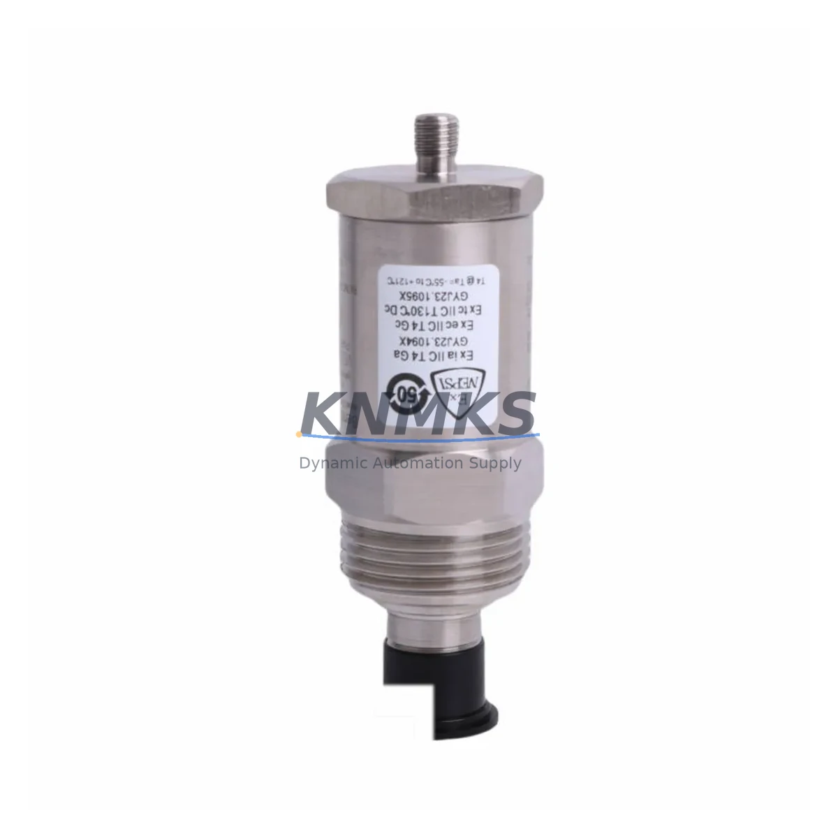
The Bently Nevada 190501-21-00-04 is an ICP®-powered Velomitor CT velocity transducer engineered for continuous vibration monitoring in rotating machinery protection systems. Designed for direct integration with Bently Nevada 3500 Series rack-based monitoring systems, this transducer delivers broadband velocity measurement across a wide frequency range, making it a critical spare for turbines, compressors, pumps, motors, and gearboxes operating in demanding industrial environments.
For maintenance engineers managing aging machinery protection infrastructure, the 190501-21-00-04 represents a drop-in replacement for worn or failed velocity sensors without requiring reconfiguration of the monitoring rack. Its ICP signal conditioning eliminates the need for external power supplies or signal conditioners in most installations, reducing wiring complexity and minimizing downtime during emergency replacement. Procurement engineers sourcing this part should confirm cable connector compatibility and verify the ICP bias voltage supplied by the connected monitor module before installation.
KNMKS maintains tested stock of the 190501-21-00-04 to support unplanned outage recovery and planned annual maintenance windows. Each unit is inspected and function-verified prior to shipment, backed by a support terms confirmed by quotation covering manufacturing defects and performance conformance to original Bently Nevada specifications.
Spare Maintenance Table
| Part Number | 190501-21-00-04 |
| Brand | Bently Nevada |
| Series | 190500 Velomitor CT Series |
| Type | ICP Velocity Transducer (Velomitor CT) |
| Measurement | Broadband velocity (vibration) |
| Signal Output | ICP (Integrated Circuit Piezoelectric) |
| Frequency Range | Approx. 2 Hz – 2,000 Hz (broadband) |
| Sensitivity | 100 mV/in/s (nominal) |
| Supply Voltage | 18–30 VDC (ICP bias via monitor) |
| Connector Type | 2-pin MIL-C-5015 style (confirm per cable assembly) |
| Housing Material | Stainless steel, hermetically sealed |
| Operating Temperature | -40°C to +121°C |
| Ingress Protection | IP67 (dust-tight, water-immersion rated) |
| Compatible Systems | Bently Nevada 3500 Series, 2300 Series monitors |
| Mounting | Stud mount (thread per installation drawing) |
| Origin | USA |
| Support terms | 12 Months — manufacturing defects & performance conformance |
| Condition | New / Tested surplus — function-verified before shipment |
Maintenance Planning for Continuous Operation
When replacing the 190501-21-00-04 Velomitor CT transducer during a scheduled or emergency maintenance event, a thorough inspection of the surrounding measurement loop is essential to prevent repeat failures and ensure signal integrity across the machinery protection system.
Begin by inspecting the Bently Nevada 330130 or 330180 series interconnect cables that carry the ICP signal from the transducer to the monitor rack. Cable jacket abrasion, connector corrosion, and shield continuity failures are common causes of spurious vibration alarms that are often misdiagnosed as transducer faults. Replace any cable showing physical damage or elevated resistance at the connector pins.
At the rack level, verify the Bently Nevada 3500/42M Velocity Monitor or equivalent velocity input module is supplying correct ICP bias voltage (typically 18–24 VDC) and that the channel is not in a latched alarm state. A failed bias supply on the monitor card can damage a newly installed transducer within minutes of power-up. If the monitor card has not been serviced in the current maintenance cycle, treat it as a co-inspection item alongside the transducer replacement.
Check the 3500 Rack Power Supply module (such as the 3500/15 or 3500/05) for output voltage stability. Voltage ripple or dropout events are a leading cause of false trips in velocity monitoring channels and can stress ICP-powered sensors over time. A spare power supply module in the maintenance kit is strongly recommended for critical machinery trains.
Inspect the 3500/20 or 3500/22 keyphasor module if the machinery train uses phase-referenced vibration analysis. A degraded keyphasor signal can corrupt vector data and make it difficult to distinguish a genuine rotor fault from a sensor replacement artifact during post-maintenance verification runs.
For installations where the Velomitor CT feeds into a System 1 Evolution or Orbit 60 Series condition monitoring platform, confirm that the transducer channel configuration (sensitivity, engineering units, full-scale range) is correctly mapped in the software after hardware replacement. Misconfigured channel scaling is a common post-maintenance oversight that generates nuisance alarms during the first operational run.
Finally, review the terminal block and field junction box connections at the machinery skid. Loose terminations, moisture ingress, and ground loops at the field end of the ICP cable are frequently overlooked during transducer replacements and can introduce noise that masks real vibration trends in the monitoring system.
Site Replacement Workflow
Step 1 — Pre-Replacement Verification: Confirm the failed or degraded transducer part number against the machinery protection drawing. Verify that the 190501-21-00-04 is the correct Velomitor CT variant for the mounting configuration, cable assembly, and monitor channel type in use. Cross-reference with the Bently Nevada 190500 series selection guide if multiple variants are installed on the same train.
Step 2 — Safe Isolation: Place the affected monitor channel in bypass mode via the 3500 rack front panel or System 1 software to prevent a spurious trip during transducer removal. Document the bypass action in the maintenance log and notify the control room operator.
Step 3 — Physical Replacement: Remove the existing transducer using the correct torque specification for the stud mount. Clean the mounting surface and inspect for corrosion or thread damage. Install the 190501-21-00-04 to the specified torque, reconnect the ICP cable, and verify connector seating and locking ring engagement.
Step 4 — Signal Verification: With the channel still in bypass, power up the transducer and measure ICP bias voltage at the cable connector using a calibrated meter. Confirm the bias level is within the monitor’s specified range before removing bypass. Observe the live vibration reading for at least 5 minutes to confirm stable, noise-free output before returning the channel to normal protection mode.
Step 5 — Documentation and Spare Replenishment: Record the replacement in the equipment maintenance history, including the new transducer serial number, installation date, and post-replacement vibration baseline. Immediately initiate a purchase order to replenish the consumed spare to maintain minimum stock levels for the next unplanned event.
Spare Parts Support FAQ
Q1: Is the 190501-21-00-04 a direct replacement for other 190500 series Velomitor CT variants?
The 190500 series includes multiple variants differentiated by connector type, cable length, and mounting configuration. The 190501-21-00-04 is a specific variant and should be matched to the original installation drawing before ordering. KNMKS can assist with cross-referencing if you provide the machinery tag number or original purchase documentation.
Q2: How is each unit tested before shipment?
Every 190501-21-00-04 unit shipped by KNMKS undergoes functional verification including ICP bias response, output signal continuity, and connector integrity checks. Units that do not meet performance thresholds are quarantined and not offered for sale. A test report summary is available upon request for critical applications.
Q3: What is the lead time and long-term supply availability?
KNMKS maintains buffer stock of the 190501-21-00-04 to support both emergency same-week shipments and planned annual maintenance procurement. For sites with multiple machinery trains using this transducer, we recommend establishing a blanket order or consignment stock arrangement to eliminate lead-time risk during peak outage seasons. Contact our team to discuss long-term supply agreements.
Q4: What does the support terms confirmed by quotation cover?
The support terms confirmed by quotation cover manufacturing defects and confirmed performance non-conformance under normal operating conditions consistent with the Bently Nevada 190500 series specification. Support requests require return of the unit for inspection. KNMKS will provide a replacement unit or documented resolution support upon confirmation of a valid support terms claim. Damage resulting from incorrect installation, overvoltage, or mechanical impact is excluded.
© 2026 KNMKS. All rights reserved.
Original Source: https://knmks.com
Contact: admin@knmks.com | +86 18359268345
Product Identification
- Brand / Ecosystem
-
Bently Nevada
Bently Nevada - Model / Series
- 190501-21-00-04
- Product Family
- Sensors
- Availability Status
- Available on request after model and quantity confirmation
- Inquiry Type
- B2B RFQ, replacement inquiry and project spare-part request
- Pre-Quote Check
- Exact SKU, brand, series, quantity, nameplate photos and destination country are checked before quotation
System Path
Where this product fits in the KNMKS automation structure.
Specification & Inquiry Focus
- Sensor range
- Photoelectric, proximity and process sensors
- Common needs
- Output type, distance and connector
- Project support
- Machine detection and replacement inquiry
Buyer Confirmation
Information KNMKS checks before replying.
- Exact model
- 190501-21-00-04
- Brand / ecosystem
- Bently Nevada
- Product family
- Sensors
- Application note
- Replacement, maintenance, project build or spare-part list
- Useful photos
- Nameplate, installed unit, cabinet layout or connector side
- Delivery details
- Quantity, destination country and target schedule
Document Support
Files and notes can be confirmed during quotation.
- Product photos or nameplate confirmation when available
- Packing and delivery notes before quotation confirmation
- Support scope and delivery terms confirmed per inquiry
- Export document coordination for qualified B2B requests
Inquiry Support
- NPN/PNP, analog and digital output checking
- Connector and cable compatibility review
- Fast inquiry support for maintenance teams
What to Send Us
- Brand and exact model number: Bently Nevada 190501-21-00-04
- Quantity and required delivery time
- Application, replacement requirement or nameplate photo
- Destination country and shipping preference
RFQ Preparation
This is a product inquiry page built for RFQ communication.
Fast Model Check
Send this model to KNMKS for confirmation.
Include quantity, destination country and photos if this is a maintenance replacement. The inquiry will be saved with a reference number after submission.
Brand & Compatibility Note
KNMKS displays automation product information for well-known industrial brand ecosystems and compatible replacement references. Brand names are used for product identification and compatibility reference only; final availability and commercial terms are confirmed per quotation.
 Manufacturing
 Machine Tools
 Packaging
 Energy & Power

 PLCs & Controllers
 HMI & Displays
 Servo Systems
 Variable Frequency Drives