
Overview
Bently Nevada 190501-21-00-01 Migration-Ready Velocity Sensor for Legacy Control Systems
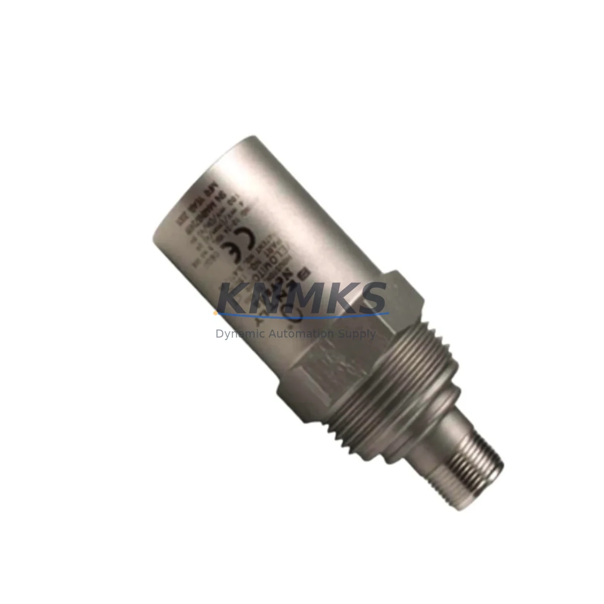
The Bently Nevada 190501-21-00-01 is a Velomitor CT seismic velocity transducer engineered for direct retrofit into existing machinery protection and condition monitoring systems. As legacy 190501-series sensors approach end-of-life or become unavailable through OEM channels, the 190501-21-00-01 provides a migration-ready replacement path that preserves original wiring configurations, signal output characteristics, and mechanical mounting geometry. This makes it a preferred choice for maintenance engineers managing rotating equipment protection on turbines, compressors, pumps, and motors where unplanned downtime carries significant operational and financial risk.
Designed to interface directly with Bently Nevada 3500-series machinery protection rack systems, the 190501-21-00-01 delivers a velocity output signal compatible with 3500/42M velocity and acceleration monitor cards without requiring firmware changes or signal conditioning modifications. Engineers replacing sensors on existing 3500 rack installations can retain the original I/O termination module wiring, reducing retrofit labor and eliminating the need for panel rewiring. The sensor’s integral cable and connector configuration matches the legacy 190501 footprint, allowing direct substitution in most field installations.
For sites running older Bently Nevada 7200-series or 3300-series monitoring systems, the 190501-21-00-01 can be integrated with appropriate signal conditioning adapters. Retrofit planning for these platforms should include a review of the existing proximitor or velocity input card specifications, confirmation of the transducer power supply voltage (typically 18–24 VDC), and verification of the output signal range against the monitor card’s input acceptance window. Where 3300-series XL monitors are in service, the migration path may also involve updating the monitor configuration software to reflect the new transducer’s sensitivity value.
Migration Compatibility Table
| Parameter | 190501-21-00-01 (This Unit) | Legacy 190501 Series | Retrofit Notes |
|---|---|---|---|
| Sensor Type | Velomitor CT Seismic Velocity | Velomitor Seismic Velocity | Direct functional replacement |
| Output Signal | 100 mV/in/s (4 mV/mm/s) | 100 mV/in/s (4 mV/mm/s) | No signal conditioning change required |
| Supply Voltage | 18–24 VDC | 18–24 VDC | Existing power supply compatible |
| Connector / Cable | Integral armored cable, MIL-C-5015 connector | Integral armored cable, MIL-C-5015 connector | Retain existing field wiring |
| Mounting Thread | 10-32 UNF stud mount | 10-32 UNF stud mount | No mechanical modification required |
| Monitor Compatibility | 3500/42M, 3300 XL, 7200-series | 3500/42M, 3300 XL, 7200-series | Verify monitor input card sensitivity setting |
| Communication Protocol | Analog 4–20 mA / voltage output | Analog 4–20 mA / voltage output | No protocol migration required |
| Installation Space | Same form factor as legacy unit | Standard Velomitor housing | Confirm clearance at mounting pad |
| Firmware / Configuration | No firmware required (passive analog) | No firmware required | Update monitor sensitivity if changed |
| Support terms | support terms confirmed by quotation — Covered against manufacturing defects and functional failure under normal operating conditions | Applies to this replacement unit | |
Retrofit Planning for Existing Automation Systems
A successful retrofit of the 190501-21-00-01 into an operating plant begins well before the physical swap. Maintenance teams should first pull the existing machinery protection system documentation to confirm which monitor card slot the velocity channel occupies within the 3500-series rack. If the rack also houses a 3500/20 rack interface module or a 3500/22M transient data interface, these modules should be checked for firmware compatibility with the replacement sensor’s output characteristics before the outage window opens.
On sites where the 3500 rack communicates upstream to a DCS via a 3500/92 communication gateway or a Modbus TCP interface card, the retrofit plan should include a signal continuity test after sensor installation to confirm that the velocity channel value is correctly mapped to the DCS historian tag. Plants using Emerson Ovation or Honeywell Experion PKS as the supervisory control layer will typically require a brief I/O verification step in the DCS engineering workstation to confirm the channel is reading within the expected engineering unit range.
For installations where the 190501-21-00-01 is being installed alongside a broader control cabinet upgrade — for example, replacing a legacy Bently Nevada 3300-series rack with a modern 3500-series rack — the retrofit scope expands to include rack power supply sizing, backplane slot assignment, and I/O termination module selection. The 3500/15 power supply module and the 3500/05 rack interface module are commonly involved in these parallel upgrades. Where multiple velocity channels are being replaced simultaneously, a channel-by-channel commissioning log should be maintained to track sensitivity values, gap voltages (where applicable), and alarm setpoint confirmations for each position.
Signal isolation requirements should also be reviewed during retrofit planning. In older installations where ground loops have been a recurring issue, adding a signal isolator between the transducer output and the monitor card input can prevent noise-induced false alarms during the transition period. Programming cable access for the 3500 rack’s configuration software (Rack Configuration Software, RCS) should be confirmed prior to the outage to allow rapid setpoint adjustments if required during commissioning.
Downtime Control During System Migration
Minimizing downtime during a velocity sensor replacement on critical rotating equipment requires a structured pre-outage preparation protocol. Before the machine is taken offline, the existing sensor output values — including vibration amplitude, alarm thresholds, and danger setpoints — should be documented from the 3500-series monitor display or the DCS historian. This baseline record allows the commissioning team to verify that the replacement 190501-21-00-01 is reading within the expected range immediately after installation, without requiring an extended run-in period.
The physical replacement itself is typically a short-duration task when the replacement sensor matches the original mounting configuration. The 190501-21-00-01’s identical stud mount thread and cable connector format means that field technicians can complete the mechanical swap, reconnect the armored cable, and restore the monitor channel to service within a single shift. Where the machine cannot be fully shut down, a hot-swap procedure may be possible on some 3500-series monitor configurations — this should be confirmed with the site’s machinery protection engineer before attempting.
After installation, the commissioning sequence should include a channel OK verification on the 3500 monitor front panel, a review of the OK relay output state, and a confirmation that the velocity reading is stable at the machine’s normal operating speed. If the site uses a System 1 condition monitoring software platform, the new sensor’s channel should be verified in the System 1 database to ensure that the trend data stream resumes without a gap. Alarm inhibit functions available in the 3500 rack can be used to suppress nuisance alerts during the brief commissioning window, reducing the risk of spurious shutdowns while the replacement sensor stabilizes.
Retrofit Support FAQ
Q1: Is the 190501-21-00-01 a direct drop-in replacement for the original 190501-series Velomitor sensors?
Yes. The 190501-21-00-01 maintains the same output sensitivity (100 mV/in/s), supply voltage range (18–24 VDC), mounting thread (10-32 UNF), and cable connector format as the original 190501-series Velomitor sensors. In most installations, no wiring changes, signal conditioning modifications, or monitor card reconfiguration are required. The only recommended verification step is to confirm the sensitivity value entered in the 3500 monitor configuration matches the replacement sensor’s specification sheet.
Q2: What commissioning steps are required after installing the 190501-21-00-01?
After mechanical installation and cable reconnection, verify the Channel OK status on the 3500 monitor front panel, confirm the velocity reading is within the expected range at operating speed, and check that alarm and danger setpoints are correctly configured. If the rack communicates to a DCS or condition monitoring platform, perform a signal continuity check to confirm the channel value is correctly received upstream. Document the as-found and as-left readings in the site’s maintenance management system.
Q3: Can this sensor be used with older 3300-series or 7200-series Bently Nevada monitoring systems?
The 190501-21-00-01 is compatible with 3300 XL and 7200-series monitor inputs, subject to confirmation of the input card’s accepted sensitivity range and supply voltage. For 3300-series installations, review the monitor card’s configuration to ensure the velocity input channel is set to accept the Velomitor CT output format. Adapter cables or signal conditioning may be required in some older 7200-series rack configurations — contact our technical team for site-specific guidance.
Q4: What does the support terms confirmed by quotation cover, and is pre-shipment testing performed?
Every 190501-21-00-01 unit is function-tested prior to shipment to verify output signal integrity, supply current draw, and mechanical integrity. The support terms confirmed by quotation cover manufacturing defects and functional failure under normal operating conditions from the date of shipment. Units that fail within the confirmed support period are replaced or repaired at no charge. Support requests should be submitted with the original order reference and a description of the failure mode observed in service.
© 2026 KNMKS. All rights reserved.
Original Source: https://knmks.com
Contact: admin@knmks.com | +86 18359268345
Product Identification
- Brand / Ecosystem
-
Bently Nevada
Bently Nevada - Model / Series
- 190501-21-00-01
- Product Family
- Sensors
- Availability Status
- Available on request after model and quantity confirmation
- Inquiry Type
- B2B RFQ, replacement inquiry and project spare-part request
- Pre-Quote Check
- Exact SKU, brand, series, quantity, nameplate photos and destination country are checked before quotation
System Path
Where this product fits in the KNMKS automation structure.
Specification & Inquiry Focus
- Sensor range
- Photoelectric, proximity and process sensors
- Common needs
- Output type, distance and connector
- Project support
- Machine detection and replacement inquiry
Buyer Confirmation
Information KNMKS checks before replying.
- Exact model
- 190501-21-00-01
- Brand / ecosystem
- Bently Nevada
- Product family
- Sensors
- Application note
- Replacement, maintenance, project build or spare-part list
- Useful photos
- Nameplate, installed unit, cabinet layout or connector side
- Delivery details
- Quantity, destination country and target schedule
Document Support
Files and notes can be confirmed during quotation.
- Product photos or nameplate confirmation when available
- Packing and delivery notes before quotation confirmation
- Support scope and delivery terms confirmed per inquiry
- Export document coordination for qualified B2B requests
Inquiry Support
- NPN/PNP, analog and digital output checking
- Connector and cable compatibility review
- Fast inquiry support for maintenance teams
What to Send Us
- Brand and exact model number: Bently Nevada 190501-21-00-01
- Quantity and required delivery time
- Application, replacement requirement or nameplate photo
- Destination country and shipping preference
RFQ Preparation
This is a product inquiry page built for RFQ communication.
Fast Model Check
Send this model to KNMKS for confirmation.
Include quantity, destination country and photos if this is a maintenance replacement. The inquiry will be saved with a reference number after submission.
Brand & Compatibility Note
KNMKS displays automation product information for well-known industrial brand ecosystems and compatible replacement references. Brand names are used for product identification and compatibility reference only; final availability and commercial terms are confirmed per quotation.
 Manufacturing
 Machine Tools
 Packaging
 Energy & Power
 PLCs & Controllers
 HMI & Displays
 Servo Systems
 Variable Frequency Drives