
Overview
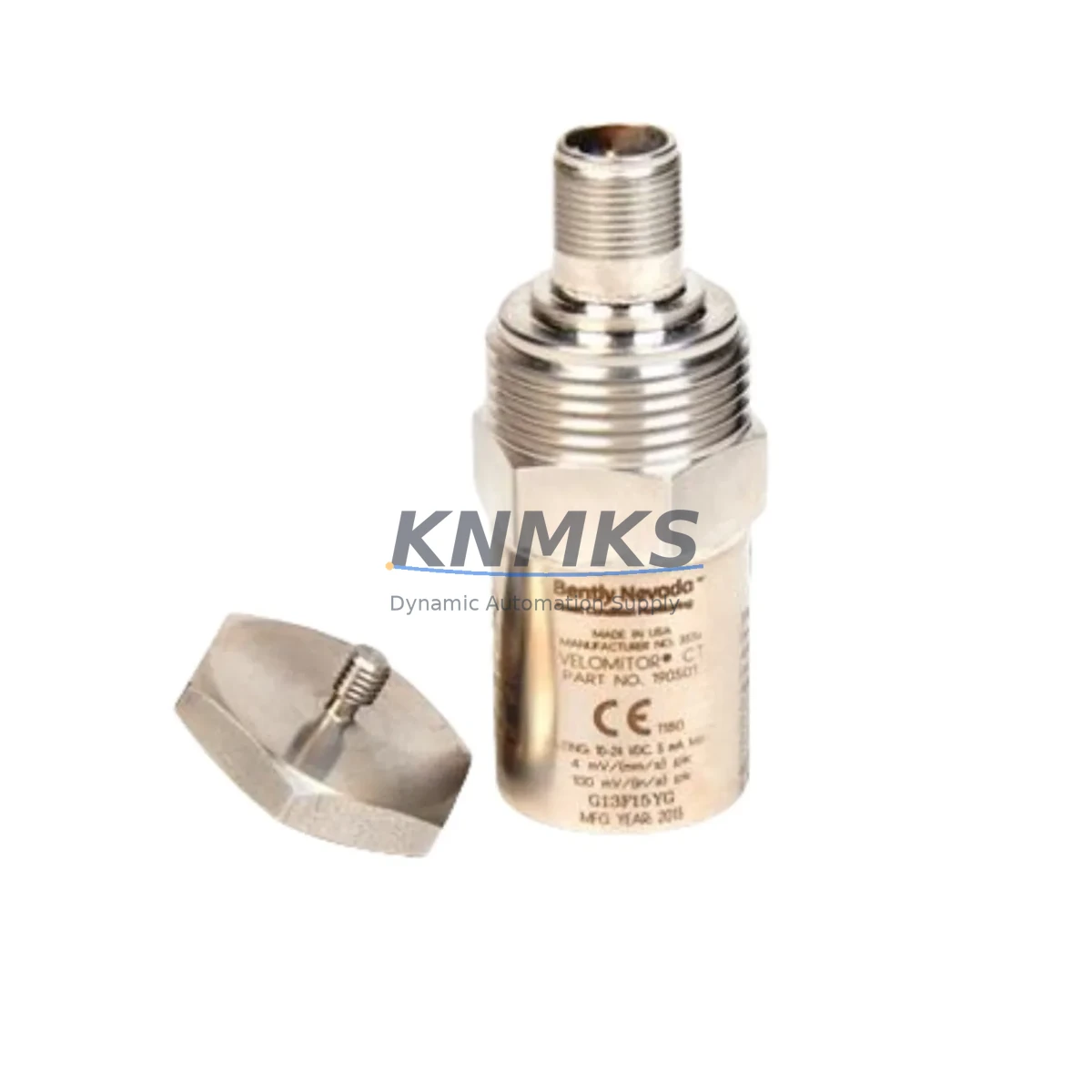
Bently Nevada 190501-21-00-00 Migration-Ready Velomitor CT for Legacy Control Systems
The Bently Nevada 190501-21-00-00 Velomitor CT is a seismic velocity transducer engineered for continuous vibration monitoring in rotating machinery protection systems. As legacy Bently Nevada installations approach end-of-life or face discontinued spare-parts availability, the 190501-21-00-00 serves as a migration-ready, drop-in replacement that preserves existing wiring infrastructure, signal conditioning architecture, and 3500 Series rack compatibility without requiring reprogramming of the host monitoring system.
This unit delivers a 4–20 mA output signal compatible with the Bently Nevada 3500 Series monitoring rack, including the 3500/42M Proximitor/Seismic Monitor module. Engineers migrating from earlier Velomitor generations or from third-party seismic sensors will find that the 190501-21-00-00 maintains the same terminal block pinout, cable shield grounding convention, and signal range expected by the 3500 rack’s I/O configuration. Before installation, maintenance teams should verify the existing junction box wiring against the transducer’s two-wire loop-powered circuit requirements and confirm that the 3500/42M channel configuration reflects the correct transducer type and full-scale range.
Each unit is pre-tested against Bently Nevada factory acceptance criteria prior to shipment, with a support terms confirmed by quotation covering manufacturing defects and signal integrity under normal operating conditions.
Migration Compatibility Table
| Parameter | Details |
|---|---|
| SKU / Part Number | 190501-21-00-00 |
| Brand / Series | Bently Nevada / Velomitor CT / 3500 Series |
| Transducer Type | Seismic Velocity (Loop-Powered, 4–20 mA) |
| Compatible Monitor Module | Bently Nevada 3500/42M Proximitor/Seismic Monitor |
| Rack Compatibility | 3500 Series Monitoring Rack (standard 19″ backplane) |
| Signal Output | 4–20 mA, two-wire loop-powered |
| Installation Interface | Terminal block wiring; existing cable reuse supported |
| Communication Protocol | Analog (4–20 mA); compatible with DCS analog input cards |
| Replacement Compatibility | Drop-in for earlier Velomitor CT variants; verify channel config in 3500/42M |
| Commissioning Requirement | Confirm full-scale range, transducer type selection, and cable continuity in 3500 rack software |
| Mounting / Installation Space | Standard Velomitor CT housing; confirm existing mounting boss thread and clearance |
| Firmware / Software | No firmware in transducer; verify 3500 rack firmware supports current I/O module revision |
| Support terms | 12 Months — covers manufacturing defects and signal integrity |
Retrofit Planning for Existing Automation Systems
A successful retrofit of the 190501-21-00-00 into an operating plant begins well before the maintenance window opens. The first step is a full audit of the existing vibration monitoring loop: trace the two-wire cable from the transducer mounting location back to the junction box and then to the 3500/42M input terminal. Confirm that cable insulation resistance meets the minimum specification and that the shield drain wire is grounded at one end only, typically at the rack end, to prevent ground loops that can corrupt the 4–20 mA signal.
Within the 3500 Series rack, the 3500/42M Proximitor/Seismic Monitor module must be configured to recognize the Velomitor CT transducer type. If the rack also hosts a 3500/22M Transient Data Interface or a 3500/32 Relay module, verify that the relay setpoints and alarm thresholds remain consistent with the new transducer’s sensitivity and full-scale velocity range. Any change in transducer sensitivity will shift the engineering-unit scaling and may trigger nuisance alarms if setpoints are not reviewed.
For plants running a DCS such as a Honeywell Experion PKS or an Emerson DeltaV, the 4–20 mA signal from the 190501-21-00-00 feeds into an analog input card. Confirm that the AI card’s input range, loop supply voltage, and HART configuration (if applicable) are compatible with a passive two-wire transmitter. If the existing loop was previously powered by an active Velomitor variant, the power supply architecture in the junction box may need adjustment.
HMI screens connected to the vibration monitoring system — whether running on a Wonderware InTouch station or a Bently Nevada System 1 software platform — should be reviewed to ensure that the tag scaling, alarm limits, and trend historian configurations reflect the replacement transducer’s output range. Updating the tag database before the physical swap reduces the risk of incorrect readings appearing on the operator display during the commissioning phase.
Where the control cabinet also houses a 3500/20 Rack Interface Module for Modbus or Ethernet/IP communication to the plant DCS, confirm that the communication link remains active during the transducer swap. If the rack must be de-energized, coordinate with the control room to place the affected channels in bypass mode within the DCS to prevent spurious shutdowns.
Downtime Control During System Migration
Minimizing unplanned downtime during a Velomitor CT replacement requires a structured pre-outage checklist. Before the maintenance window, download and archive the current 3500 rack configuration using Bently Nevada’s Rack Configuration software. This backup preserves all channel assignments, alarm setpoints, relay logic, and communication parameters, ensuring that the configuration can be restored in minutes if the rack requires a reset during the swap.
During the physical replacement, keep the 3500/42M module in its slot and isolate only the affected channel rather than removing the entire I/O module. This approach maintains monitoring continuity on adjacent channels and avoids disrupting the Modbus or Ethernet/IP communication link to the DCS. Once the 190501-21-00-00 is installed and the terminal connections are torqued to specification, perform a loop check by injecting a known current at the junction box and verifying the reading at the 3500 rack display and at the DCS operator station simultaneously.
After the loop check passes, restore the channel from bypass mode and observe the live vibration reading against the machine’s baseline trend. If the reading deviates from the historical baseline by more than the expected tolerance, re-examine the transducer mounting torque, the cable shield grounding, and the channel scaling in the 3500/42M configuration before returning the machine to full load. This structured commissioning sequence protects the original program logic, maintains field control continuity, and reduces the risk of a forced shutdown caused by a misconfigured replacement transducer.
Retrofit Support FAQ
Q1: Is the 190501-21-00-00 a direct drop-in replacement for earlier Velomitor CT models?
In most installations, yes. The 190501-21-00-00 shares the same housing dimensions, two-wire loop-powered interface, and 4–20 mA output as earlier Velomitor CT variants. However, you should verify the transducer type selection in the 3500/42M channel configuration and confirm that the full-scale velocity range matches your existing setpoints before returning the channel to service.
Q2: What commissioning steps are required after installation?
Perform a cable continuity and insulation resistance check, verify the 3500/42M channel configuration (transducer type, full-scale range, alarm setpoints), conduct a loop current injection test at the junction box, and confirm the live reading at both the 3500 rack and the DCS operator station. Archive the final rack configuration after commissioning is complete.
Q3: Can the existing field cable be reused?
Yes, provided the cable passes an insulation resistance test and the shield grounding convention (single-end ground at the rack) is maintained. Reusing the existing cable eliminates the need for re-pulling and re-labeling, which significantly reduces installation time and downtime exposure.
Q4: What does the support terms confirmed by quotation cover, and how quickly can units ship?
The support terms confirmed by quotation cover manufacturing defects and signal integrity under normal operating conditions from the date of shipment. Units are held availability confirmed by RFQ and can typically ship within 1–3 business days. For urgent requirements, contact our sales team to confirm current inventory availability and expedited shipping options.
© 2026 KNMKS. All rights reserved.
Original Source: https://knmks.com
Contact: admin@knmks.com | +86 18359268345
Product Identification
- Brand / Ecosystem
-
Bently Nevada
Bently Nevada - Model / Series
-
190501-21-00-00
3500 Series - Product Family
- Sensors
- Availability Status
- Available on request after model and quantity confirmation
- Inquiry Type
- B2B RFQ, replacement inquiry and project spare-part request
- Pre-Quote Check
- Exact SKU, brand, series, quantity, nameplate photos and destination country are checked before quotation
System Path
Where this product fits in the KNMKS automation structure.
Specification & Inquiry Focus
- Sensor range
- Photoelectric, proximity and process sensors
- Common needs
- Output type, distance and connector
- Project support
- Machine detection and replacement inquiry
Buyer Confirmation
Information KNMKS checks before replying.
- Exact model
- 190501-21-00-00
- Brand / ecosystem
- Bently Nevada
- Product family
- Sensors
- Application note
- Replacement, maintenance, project build or spare-part list
- Useful photos
- Nameplate, installed unit, cabinet layout or connector side
- Delivery details
- Quantity, destination country and target schedule
Document Support
Files and notes can be confirmed during quotation.
- Product photos or nameplate confirmation when available
- Packing and delivery notes before quotation confirmation
- Support scope and delivery terms confirmed per inquiry
- Export document coordination for qualified B2B requests
Inquiry Support
- NPN/PNP, analog and digital output checking
- Connector and cable compatibility review
- Fast inquiry support for maintenance teams
What to Send Us
- Brand and exact model number: Bently Nevada 190501-21-00-00
- Quantity and required delivery time
- Application, replacement requirement or nameplate photo
- Destination country and shipping preference
RFQ Preparation
This is a product inquiry page built for RFQ communication.
Fast Model Check
Send this model to KNMKS for confirmation.
Include quantity, destination country and photos if this is a maintenance replacement. The inquiry will be saved with a reference number after submission.
Brand & Compatibility Note
KNMKS displays automation product information for well-known industrial brand ecosystems and compatible replacement references. Brand names are used for product identification and compatibility reference only; final availability and commercial terms are confirmed per quotation.
 Manufacturing
 Machine Tools
 Packaging
 Energy & Power

 PLCs & Controllers
 HMI & Displays
 Servo Systems
 Variable Frequency Drives