
Overview
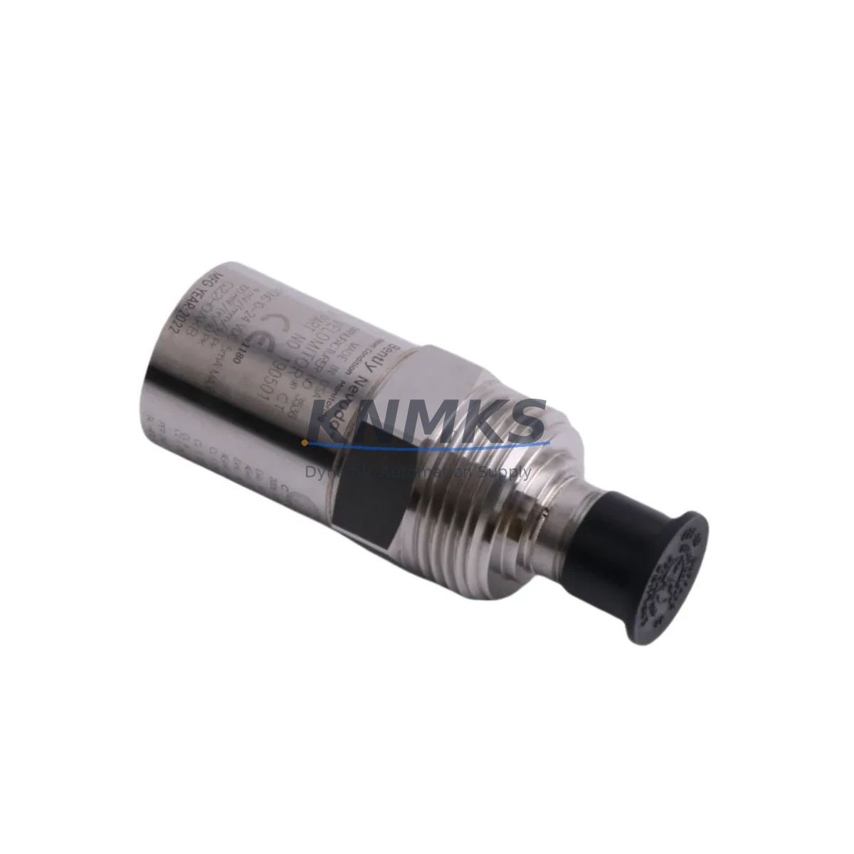
Bently Nevada 190501-20-00-CN Migration-Ready Velocity Transducer for Legacy Control Systems
The Bently Nevada 190501-20-00-CN is a Velomitor CT piezo-velocity transducer engineered for continuous vibration monitoring in rotating machinery applications. As legacy 3500 series installations approach end-of-support milestones, maintenance engineers and reliability teams are increasingly sourcing migration-ready replacements that preserve existing wiring infrastructure, rack architecture, and monitoring logic without requiring a full system overhaul. The 190501-20-00-CN delivers exactly that: a drop-in compatible unit that integrates directly into Bently Nevada 3500 series monitoring racks, retains the standard 4–20 mA output signal, and eliminates the need to reconfigure upstream DCS or SCADA data acquisition channels.
This transducer is rated for industrial environments with high vibration, temperature cycling, and continuous duty cycles. Its compact stainless-steel housing and integral cable assembly are designed to match the original mounting footprint, reducing installation time during planned outages or emergency replacements. For facilities running Bently Nevada 3500/42M or 3500/45 vibration monitor modules, the 190501-20-00-CN slots into the existing signal chain without requiring firmware updates or channel recalibration at the monitor card level.
Migration Compatibility Table
| Parameter | 190501-20-00-CN Specification | Retrofit Notes |
|---|---|---|
| Output Signal | 4–20 mA (velocity proportional) | Direct replacement for legacy Velomitor CT wiring; no signal conditioner change required |
| Rack Compatibility | Bently Nevada 3500 Series | Compatible with 3500/42M, 3500/45 monitor modules; verify slot addressing before installation |
| Mounting Interface | Standard Velomitor CT footprint | Drop-in mechanical fit; confirm thread engagement and torque spec per OEM documentation |
| Cable / Connector | Integral cable, MIL-spec connector | Match existing junction box termination; inspect shield continuity before energizing |
| Power Supply | 18–30 VDC (loop-powered) | Verify barrier or isolator output voltage at terminal block before connection |
| Communication Protocol | Analog 4–20 mA (passive loop) | No protocol migration required; DCS analog input card retains existing scaling |
| Firmware / Configuration | No firmware (passive transducer) | No firmware update needed; monitor card full-scale and alert setpoints remain unchanged |
| Commissioning Check | Static mA output verification + live vibration baseline | Perform loop check at 0 g and compare baseline spectrum against historical trend data |
| Support terms | 12 Months | Covers manufacturing defects; includes pre-shipment functional test certificate |
Retrofit Planning for Existing Automation Systems
Successful integration of the 190501-20-00-CN into a running plant begins well before the unit arrives on site. Retrofit planning should start with a full audit of the existing 3500 series rack configuration. Engineers should document each occupied slot, confirm the monitor module type (commonly the 3500/42M four-channel velocity monitor or the 3500/45 position monitor), and verify that the channel assigned to the outgoing transducer is correctly mapped in the System 1 or Rack Configuration Software database. Any mismatch between the physical channel address and the software tag will cause false alerts or missed trips during the commissioning window.
Terminal block wiring is the next critical checkpoint. The 190501-20-00-CN uses a standard two-wire loop connection at the field junction box. Before disconnecting the old unit, photograph the existing termination and record wire colors, shield drain routing, and barrier or isolator model numbers. Facilities using MTL or P+F Zener barriers should confirm that the barrier’s maximum output current and voltage remain within the transducer’s loop-power specification. If the installation includes a 3500/20 rack power monitor or a 3500/15 power supply module, verify that the aggregate current draw across all channels remains within the rack’s rated capacity after the swap.
For plants that have already migrated their historian or condition monitoring platform to OSIsoft PI or Aspentech Mtell, the 4–20 mA signal from the 190501-20-00-CN feeds directly into the existing analog input card without any driver or tag reconfiguration. However, if the facility is running an older Bently Nevada 3300 series rack in parallel for redundancy, engineers should note that the 3300 and 3500 series use different backplane connector pinouts, and the 190501-20-00-CN is not backplane-compatible with 3300 series monitor cards. In that scenario, a parallel upgrade of the 3300 rack to a 3500/01 or 3500/05 rack interface module may be required before the transducer swap can proceed.
I/O expansion projects that add new measurement points alongside the transducer replacement should also account for the 3500 rack’s available slot count. If the rack is fully populated, a secondary 3500/01 rack with a 3500/05 system interface module can extend the monitoring network without disrupting the primary rack’s communication link to the DCS. Programming cable access via the RS-232 or Ethernet port on the 3500/20 rack interface should be confirmed before the maintenance window begins, as configuration changes to alert setpoints or full-scale values require a live connection to Rack Configuration Software.
HMI screen updates are often overlooked during transducer replacements. If the plant HMI displays a dedicated faceplate for the replaced measurement point, the engineering team should verify that the tag name, engineering unit label, and alarm band displayed on the HMI match the new transducer’s calibrated output range. For facilities using Wonderware InTouch or Rockwell FactoryTalk View, this typically requires a brief tag database update and a screen publish cycle, which can be completed during the same maintenance window as the physical swap.
Downtime Control During System Migration
Minimizing unplanned downtime during a transducer replacement on a live rotating machine requires a structured pre-outage checklist and a clearly defined rollback plan. The recommended approach is to schedule the 190501-20-00-CN installation during a planned maintenance window aligned with the machine’s next lubrication or inspection interval, rather than forcing an emergency shutdown. This allows the maintenance team to pre-stage all required materials — including the replacement transducer, a calibrated loop calibrator, a spare MIL-spec connector, and the appropriate torque wrench — at the work site before the machine is de-energized.
Once the machine is safely isolated and locked out, the sequence should follow a defined swap protocol: (1) record the live mA output of the outgoing transducer as a baseline reference; (2) disconnect and label the field wiring at the junction box; (3) remove the old transducer and inspect the mounting surface for thread damage or contamination; (4) install the 190501-20-00-CN to the specified torque value; (5) reconnect field wiring per the recorded termination photograph; (6) perform a static loop check using a loop calibrator to verify 4 mA at 0 g and confirm the monitor card reads correctly in Rack Configuration Software; (7) release the machine for restart and monitor the live vibration trend for the first 30 minutes of operation against the historical baseline.
If the monitor card generates a transducer fault or out-of-range alert immediately after restart, the most common causes are an open shield connection, a reversed polarity at the barrier, or an incorrect full-scale setting in the monitor module configuration. Each of these can be resolved without a second machine shutdown if the rack’s Ethernet configuration port remains accessible during operation. Keeping the original program logic and DCS tag structure intact throughout the swap ensures that the control system’s protective trip logic remains active and that no safety interlock is inadvertently bypassed during the commissioning period.
For facilities with redundant transducer installations on the same measurement plane, the 190501-20-00-CN can be installed on the secondary channel while the primary channel remains in service, allowing a live comparison between the new and existing units before the primary is switched over. This approach effectively reduces the risk window to zero for the most critical measurement points and is strongly recommended for high-speed compressors, turbines, and pumps where a missed vibration event carries significant consequence.
Retrofit Support FAQ
Q1: Is the 190501-20-00-CN a direct drop-in replacement for the original Bently Nevada Velomitor CT?
Yes. The 190501-20-00-CN is manufactured to the same mechanical and electrical specification as the original Velomitor CT. It uses the same mounting thread, the same MIL-spec connector, and the same 4–20 mA loop-powered output. No wiring changes, no monitor card reconfiguration, and no DCS tag updates are required for a like-for-like swap in a 3500 series rack.
Q2: What commissioning steps are required after installation?
After physical installation and wiring reconnection, perform a static loop check with a calibrated loop calibrator to confirm 4 mA output at rest. Then verify the monitor card reading in Rack Configuration Software matches the expected engineering unit value. Once the machine is restarted, compare the live vibration spectrum against the historical baseline stored in System 1 or your condition monitoring historian for the first operational cycle.
Q3: Can this transducer be used with a Bently Nevada 3300 series rack?
No. The 190501-20-00-CN is designed for the 3500 series backplane and monitor card architecture. The 3300 series uses a different backplane connector pinout and a different signal conditioning approach. If your facility operates a 3300 series rack, a rack upgrade to the 3500 platform — using a 3500/01 rack and 3500/05 system interface module — is required before this transducer can be integrated.
Q4: What does the support terms confirmed by quotation cover, and is a test certificate included?
The support terms confirmed by quotation cover all manufacturing defects in materials and workmanship from the date of shipment. Every unit shipped by KNMKS undergoes a pre-shipment functional test, and a test certificate is included with the delivery documentation. Support requests are processed through admin@knmks.com with a description of the fault and the original order reference. Replacement or repair is completed within the agreed lead time, and in-stock units are typically dispatched within 3–5 business days.
© 2026 KNMKS. All rights reserved.
Original Source: https://knmks.com
Contact: admin@knmks.com | +86 18359268345
Product Identification
- Brand / Ecosystem
-
Bently Nevada
Bently Nevada - Model / Series
-
190501-20-00-CN
3500 Series - Product Family
- Sensors
- Availability Status
- Available on request after model and quantity confirmation
- Inquiry Type
- B2B RFQ, replacement inquiry and project spare-part request
- Pre-Quote Check
- Exact SKU, brand, series, quantity, nameplate photos and destination country are checked before quotation
System Path
Where this product fits in the KNMKS automation structure.
Specification & Inquiry Focus
- Sensor range
- Photoelectric, proximity and process sensors
- Common needs
- Output type, distance and connector
- Project support
- Machine detection and replacement inquiry
Buyer Confirmation
Information KNMKS checks before replying.
- Exact model
- 190501-20-00-CN
- Brand / ecosystem
- Bently Nevada
- Product family
- Sensors
- Application note
- Replacement, maintenance, project build or spare-part list
- Useful photos
- Nameplate, installed unit, cabinet layout or connector side
- Delivery details
- Quantity, destination country and target schedule
Document Support
Files and notes can be confirmed during quotation.
- Product photos or nameplate confirmation when available
- Packing and delivery notes before quotation confirmation
- Support scope and delivery terms confirmed per inquiry
- Export document coordination for qualified B2B requests
Inquiry Support
- NPN/PNP, analog and digital output checking
- Connector and cable compatibility review
- Fast inquiry support for maintenance teams
What to Send Us
- Brand and exact model number: Bently Nevada 190501-20-00-CN
- Quantity and required delivery time
- Application, replacement requirement or nameplate photo
- Destination country and shipping preference
RFQ Preparation
This is a product inquiry page built for RFQ communication.
Fast Model Check
Send this model to KNMKS for confirmation.
Include quantity, destination country and photos if this is a maintenance replacement. The inquiry will be saved with a reference number after submission.
Brand & Compatibility Note
KNMKS displays automation product information for well-known industrial brand ecosystems and compatible replacement references. Brand names are used for product identification and compatibility reference only; final availability and commercial terms are confirmed per quotation.
 Manufacturing
 Machine Tools
 Packaging
 Energy & Power

 PLCs & Controllers
 HMI & Displays
 Servo Systems
 Variable Frequency Drives