
Overview
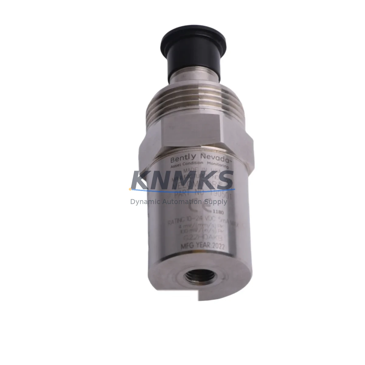
Bently Nevada 190501-18-00-CN Migration-Ready Velomitor CT: Legacy System Retrofit and Compatibility Upgrade
The Bently Nevada 190501-18-00-CN Velomitor CT is a high-output velocity transducer engineered for continuous vibration monitoring in rotating machinery applications. As legacy Bently Nevada 3500 Series monitoring systems approach end-of-service milestones, maintenance engineers and reliability teams face increasing pressure to source migration-ready replacements that preserve existing wiring infrastructure, signal conditioning chains, and rack-level integration without triggering a full system overhaul. The 190501-18-00-CN is a direct-fit, migration-ready solution designed to address exactly this challenge.
This unit delivers a nominal sensitivity of 100 mV/in/s (4 mV/mm/s), operating across a frequency range of 2 to 1000 Hz, with a broadband output compatible with the 3500/42M Proximitor/Seismic Monitor and the 3500/45 Position Monitor input channels. The integral 9-meter (30-foot) armored cable with CN-style connector terminates directly into existing field junction boxes without re-termination, making it a preferred choice for brownfield retrofit projects where minimizing downtime is a primary constraint.
When planning a retrofit involving the 190501-18-00-CN, engineers must verify several critical parameters before committing to installation. Power supply capacity at the rack level — typically sourced from a 3500/20 or 3500/25 Power Supply module — must be confirmed to support the additional transducer load if the replacement is part of a broader channel expansion. Terminal block wiring at the I/O module must be inspected for correct polarity and shield grounding, particularly when replacing older 330500 or 330525 series velocity transducers that may have used different shielding conventions. Backplane slot addressing within the 3500 rack must be validated against the existing system configuration file to ensure the replacement channel maps correctly to the operator’s DCS or SCADA historian tag structure.
Program compatibility is another key consideration. If the host system is a Honeywell Experion PKS or an Emerson DeltaV SIS platform receiving vibration data via Modbus or OPC-DA from the 3500 rack, the tag mapping and alarm setpoint configuration stored in the monitoring system’s database must be reviewed. A mismatch between the new transducer’s sensitivity and the previously configured full-scale range in the 3500/42M monitor card can result in false alarms or suppressed trip signals during the commissioning window. HMI faceplate displays on Wonderware InTouch or Yokogawa CENTUM VP operator stations should be verified to confirm that engineering unit scaling reflects the updated transducer output.
Communication link integrity between the 3500 rack and the plant DCS should be tested prior to returning the machine to service. Where the 3500 rack communicates via a 3500/92 or 3500/93 Communication Gateway module using Modbus RTU or Ethernet/IP, the gateway configuration file must be re-validated after any channel reassignment. Installation space within the control cabinet or field enclosure should be confirmed, as the 190501-18-00-CN’s cable routing and connector orientation may differ slightly from the unit being replaced. Firmware version compatibility between the 3500/42M monitor card and the replacement transducer should be confirmed with the system’s current firmware revision log before energizing the channel.
Field commissioning for the 190501-18-00-CN typically involves a bench verification of output sensitivity using a calibrated shaker table or reference signal generator before installation, followed by a live comparison against adjacent healthy channels once the machine is returned to normal operating speed. This two-stage verification approach reduces the risk of undetected wiring faults and confirms that the replacement unit is performing within the expected ±5% sensitivity tolerance band specified for 3500 Series monitor card inputs.
All units supplied by KNMKS are tested prior to shipment and covered by a support terms confirmed by quotation against manufacturing defects. Stock is maintained across regional warehouses to support urgent maintenance requirements and minimize lead-time exposure for critical rotating machinery applications.
Migration Compatibility Table
| Parameter | 190501-18-00-CN (This Unit) | Legacy / Replaced Units | Notes |
|---|---|---|---|
| Sensitivity | 100 mV/in/s (4 mV/mm/s) | 330500 / 330525 Series | Verify monitor card full-scale range setting |
| Frequency Range | 2 – 1000 Hz | Varies by legacy model | Confirm alarm setpoint scaling in 3500/42M |
| Cable Length | 9 m (30 ft) armored | Varies (5 m / 9 m options) | Confirm field routing clearance |
| Connector Type | CN-style integral connector | MIL-C-5015 or bare leads | Re-termination may be required for non-CN legacy units |
| Rack Compatibility | Bently Nevada 3500 Series | 3300 / 7200 Series (with adapter) | 3300 Series requires signal conditioner adapter |
| Monitor Card Interface | 3500/42M, 3500/45 | 3500/40M (legacy) | Confirm I/O module firmware revision |
| Communication Protocol | Modbus RTU / Ethernet/IP via 3500/92–93 | Modbus RTU (3500/92) | Re-validate gateway config after channel reassignment |
| Installation Space | Standard 3500 rack slot | Standard 3500 rack slot | Confirm cable routing and connector clearance |
| Firmware Compatibility | 3500/42M Rev. D and above | Rev. B / C (check compatibility) | Firmware upgrade may be required for Rev. B cards |
| Commissioning Requirement | Bench sensitivity verification + live channel comparison | Live channel comparison only | Two-stage verification recommended |
| Support terms | 12 Months | N/A (discontinued) | Covers manufacturing defects; pre-shipment tested |
Retrofit Planning for Existing Automation Systems
A successful retrofit involving the 190501-18-00-CN requires a structured review of the surrounding automation architecture. In most 3500 Series installations, the velocity transducer operates alongside a 3500/20 Power Supply module that feeds the rack’s I/O channels. Before replacing the transducer, the power budget for the affected rack should be recalculated, particularly if the retrofit is part of a broader channel expansion that adds new 3500/42M monitor cards or 3500/32M 4-Channel Relay modules to the same rack.
Terminal block wiring at the field junction box and at the 3500 I/O module’s rear terminal block must be inspected and documented before disconnecting the legacy unit. In installations where the original transducer was wired using a 3500/15 or 3500/20 I/O module with a dedicated terminal block adapter, the replacement wiring diagram must be confirmed against the current I/O module revision to avoid polarity reversal or shield grounding errors that can introduce noise into the vibration signal chain.
Where the 3500 rack communicates with a Yokogawa CENTUM VP DCS or a Siemens SIMATIC PCS 7 system via OPC-DA or Modbus TCP, the historian tag structure and alarm management configuration must be reviewed before the replacement channel is brought online. In plants running Emerson AMS Device Manager for condition monitoring, the asset record for the replaced transducer should be updated to reflect the new model number and calibration date to maintain audit trail integrity.
For installations where the 190501-18-00-CN replaces a unit in a dual-voting or 2oo3 voting logic configuration — common in safety-instrumented systems governed by IEC 61511 — the SIS logic solver’s bypass and inhibit procedures must be followed during the replacement window to prevent spurious trips. The 3500/32M relay module’s output state should be confirmed in bypass mode before disconnecting the legacy transducer, and the voting logic should be re-enabled and tested after the replacement unit is commissioned and verified.
Programming cable access to the 3500 rack via a 3500/93 Ethernet module or a direct RS-232 connection to the rack’s front-panel port may be required to update the system configuration file after channel reassignment. The Bently Nevada System 1 software or the 3500 Rack Configuration software should be used to verify that the replacement channel’s sensitivity, full-scale range, and alarm setpoints are correctly configured before returning the machine to service.
Downtime Control During System Migration
Minimizing downtime during a 190501-18-00-CN replacement requires advance preparation that begins well before the maintenance window opens. The replacement unit should be bench-tested and verified against a calibration reference before the machine is taken offline, so that installation and wiring can be completed without delays caused by unit verification on-site.
The existing system configuration file from the 3500 rack should be backed up to a secure location before any wiring changes are made. This backup preserves the channel configuration, alarm setpoints, and communication gateway settings that would otherwise need to be manually re-entered if the configuration is lost during the replacement process. Where the rack communicates with a DCS historian, the historian’s data collection for the affected tag should be placed in manual or substitute mode to prevent gap-filling errors in the process data record during the maintenance window.
Field control continuity can be maintained during the replacement window by confirming that adjacent healthy channels in the same rack continue to provide valid vibration data to the DCS or SCADA system. In installations where the 190501-18-00-CN monitors a non-critical bearing position, the machine may be able to remain in service on reduced monitoring coverage during the replacement, subject to the plant’s risk assessment and safety management procedures.
After installation, a live channel comparison against adjacent healthy channels at normal operating speed provides a rapid confirmation that the replacement unit is performing correctly before the maintenance window is formally closed. This approach reduces the risk of returning a machine to service with an undetected wiring fault or sensitivity error, and supports the goal of maintaining field control continuity throughout the retrofit process.
Retrofit Support FAQ
Q1: Is the 190501-18-00-CN a direct drop-in replacement for the 330500 and 330525 Series velocity transducers?
The 190501-18-00-CN is functionally compatible with 3500/42M and 3500/45 monitor card inputs and can replace 330500 and 330525 Series units in most applications. However, the CN-style connector and cable length must be confirmed against the field installation before ordering. In some legacy installations, a re-termination adapter or cable extension may be required to match the original wiring configuration.
Q2: What commissioning steps are required after installing the 190501-18-00-CN?
After installation, the channel configuration in the 3500 rack should be verified using the Bently Nevada 3500 Rack Configuration software to confirm that sensitivity, full-scale range, and alarm setpoints match the replacement unit’s specifications. A live channel comparison against adjacent healthy channels at normal operating speed is recommended before closing the maintenance window. Where the rack communicates with a DCS or SCADA system, the historian tag and alarm management configuration should be verified to confirm that the replacement channel is reporting correctly.
Q3: How is inventory availability and lead time managed for the 190501-18-00-CN?
KNMKS maintains regional warehouse stock of the 190501-18-00-CN to support urgent maintenance requirements. Standard lead time for in-stock units is 3–7 business days for international shipments. For critical applications with long-term maintenance requirements, blanket stock arrangements are available to reserve inventory against planned maintenance schedules and reduce lead-time exposure.
Q4: What does the support terms confirmed by quotation cover, and how is it supported?
All 190501-18-00-CN units supplied by KNMKS are covered by a support terms confirmed by quotation against manufacturing defects from the date of shipment. Each unit is tested prior to shipment to verify sensitivity and output performance. Support requests are supported by KNMKS’s technical team, and replacement units can be dispatched from regional warehouse stock to minimize downtime in the event of a support terms-covered failure.
© 2026 KNMKS. All rights reserved.
Original Source: https://knmks.com
Contact: admin@knmks.com | +86 18359268345
Product Identification
- Brand / Ecosystem
-
Bently Nevada
Bently Nevada - Model / Series
-
190501-18-00-CN
3500 Series - Product Family
- Sensors
- Availability Status
- Available on request after model and quantity confirmation
- Inquiry Type
- B2B RFQ, replacement inquiry and project spare-part request
- Pre-Quote Check
- Exact SKU, brand, series, quantity, nameplate photos and destination country are checked before quotation
System Path
Where this product fits in the KNMKS automation structure.
Specification & Inquiry Focus
- Sensor range
- Photoelectric, proximity and process sensors
- Common needs
- Output type, distance and connector
- Project support
- Machine detection and replacement inquiry
Buyer Confirmation
Information KNMKS checks before replying.
- Exact model
- 190501-18-00-CN
- Brand / ecosystem
- Bently Nevada
- Product family
- Sensors
- Application note
- Replacement, maintenance, project build or spare-part list
- Useful photos
- Nameplate, installed unit, cabinet layout or connector side
- Delivery details
- Quantity, destination country and target schedule
Document Support
Files and notes can be confirmed during quotation.
- Product photos or nameplate confirmation when available
- Packing and delivery notes before quotation confirmation
- Support scope and delivery terms confirmed per inquiry
- Export document coordination for qualified B2B requests
Inquiry Support
- NPN/PNP, analog and digital output checking
- Connector and cable compatibility review
- Fast inquiry support for maintenance teams
What to Send Us
- Brand and exact model number: Bently Nevada 190501-18-00-CN
- Quantity and required delivery time
- Application, replacement requirement or nameplate photo
- Destination country and shipping preference
RFQ Preparation
This is a product inquiry page built for RFQ communication.
Fast Model Check
Send this model to KNMKS for confirmation.
Include quantity, destination country and photos if this is a maintenance replacement. The inquiry will be saved with a reference number after submission.
Brand & Compatibility Note
KNMKS displays automation product information for well-known industrial brand ecosystems and compatible replacement references. Brand names are used for product identification and compatibility reference only; final availability and commercial terms are confirmed per quotation.
 Manufacturing
 Machine Tools
 Packaging
 Energy & Power

 PLCs & Controllers
 HMI & Displays
 Servo Systems
 Variable Frequency Drives