
Overview
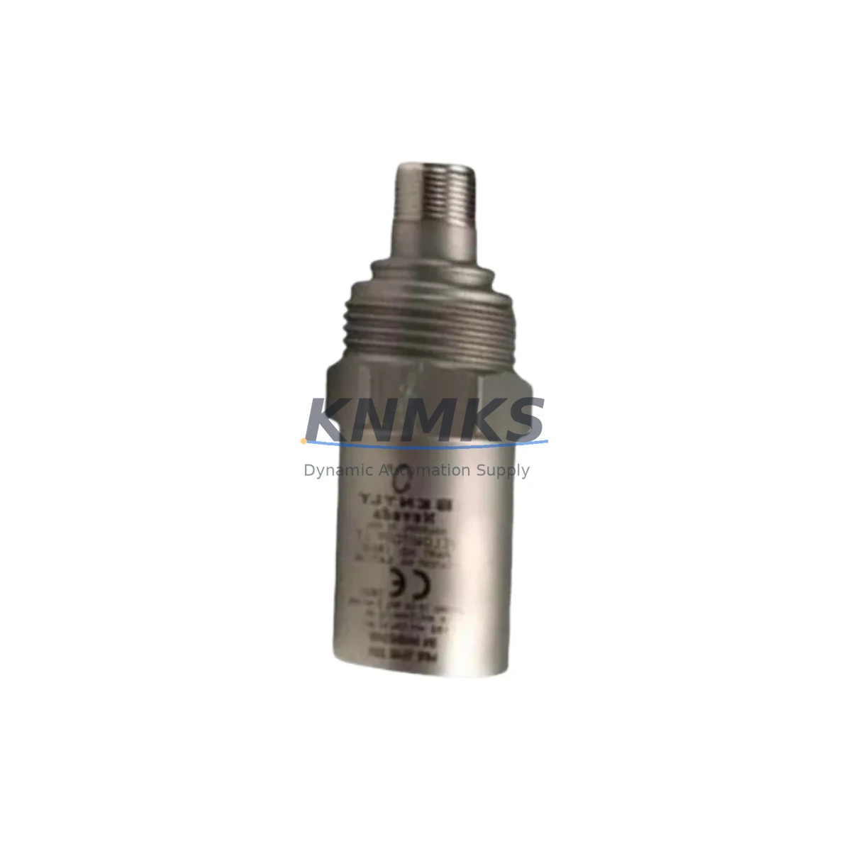
Bently Nevada 190501-14-99-01 Spare Part for Factory Uptime
The Bently Nevada 190501-14-99-01 is a Velomitor CT piezo-velocity transducer engineered for continuous vibration monitoring in rotating machinery applications. Designed for direct integration with Bently Nevada 3300 XL and System 1 condition monitoring platforms, this velocity transducer delivers reliable, high-sensitivity seismic velocity measurements across a broad frequency range — making it a critical spare for any maintenance program targeting unplanned downtime elimination.
As an original-specification replacement, the 190501-14-99-01 maintains full backward compatibility with existing Velomitor CT installations. Its rugged stainless steel housing and hermetically sealed design ensure stable performance in harsh industrial environments including petrochemical plants, power generation facilities, compressor stations, and heavy manufacturing lines. Maintenance engineers and MRO procurement teams rely on this part to restore vibration monitoring loops quickly, without requiring recalibration or system reconfiguration.
KNMKS maintains verified stock of the 190501-14-99-01 with pre-shipment functional testing, ensuring every unit dispatched meets original Bently Nevada performance specifications. Each unit is covered by a support terms confirmed by quotation from date of shipment, supporting both emergency replacement and planned annual overhaul programs.
Spare Maintenance Table
| Part Number | 190501-14-99-01 |
| Brand | Bently Nevada (Baker Hughes) |
| Series | Velomitor CT |
| Product Type | Piezo-Velocity Transducer |
| Measurement | Seismic Velocity (mm/s or in/s) |
| Frequency Range | Approx. 2 Hz – 1,000 Hz |
| Output Signal | Velocity (integrated from internal accelerometer) |
| Housing Material | Stainless Steel, Hermetically Sealed |
| Mounting | Stud mount / magnetic base compatible |
| Compatible Systems | Bently Nevada 3300 XL, System 1, TDXnet |
| Compatible Monitors | 3300/16, 3300/20, 3300/55 Velocity Monitor |
| Operating Temperature | -40°C to +121°C |
| IP Rating | IP67 (dust-tight, water-immersion resistant) |
| Origin | USA |
| Condition | New / Surplus New |
| Pre-Shipment Test | Functional verification included |
| Support terms | 12 Months from date of shipment |
| Lead Time | availability confirmed by RFQ — ships within 2–5 business days |
Maintenance Planning for Continuous Operation
When replacing the 190501-14-99-01 Velomitor CT transducer during a scheduled outage or emergency callout, a thorough inspection of the surrounding monitoring loop is essential to prevent repeat failures and ensure measurement integrity upon restart.
Begin with the transducer cable and connector assembly — the Bently Nevada 330130 or 330180 series extension cables are commonly paired with Velomitor CT installations. Inspect for jacket abrasion, connector corrosion, and shield continuity. A degraded cable can introduce noise into the velocity signal and trigger false alarms on the 3300 XL monitor rack.
Next, verify the 3300/55 Velocity Monitor module or equivalent rack card. Check the OK relay output, alarm setpoints, and buffered output voltage. If the monitor has been in service for more than five years, consider scheduling a module swap during the same maintenance window to avoid a second outage. The 3300/16 Power Supply module feeding the rack should also be inspected — measure output voltage under load and confirm the OK LED status. A marginal power supply is a common root cause of intermittent transducer faults that are misdiagnosed as sensor failures.
For installations using Bently Nevada 3500 series racks in parallel or as a migration target, confirm that the velocity input card (3500/42M or 3500/45) is configured for the correct transducer type and sensitivity. Mismatched configuration will produce erroneous vibration readings even with a new 190501-14-99-01 installed.
Inspect the junction box and terminal blocks at the field end. Loose terminations on the signal and shield conductors are a frequent source of intermittent faults in high-vibration environments. Torque all terminals to specification and apply anti-corrosion compound where moisture ingress is a risk. If the installation uses signal isolators or barriers between the transducer and the monitor rack — common in hazardous area (Zone 1/Zone 2) installations — verify that the isolator’s frequency response and signal attenuation are within acceptable limits for velocity measurement.
Finally, review the System 1 software configuration for the measurement point associated with this transducer. Confirm that the transducer sensitivity factor, alarm thresholds, and OK limits are correctly entered. An incorrect sensitivity value will cause the system to misreport actual vibration severity, undermining the entire condition monitoring program.
Site Replacement Workflow
Step 1 — Isolation and Lockout: Follow site LOTO procedures. Isolate the monitor rack channel associated with the 190501-14-99-01 installation point. Note the current OK/Not-OK status and any active alarms before disconnecting.
Step 2 — Cable Disconnection: Disconnect the extension cable at the transducer end. Label the cable with the measurement point ID before removal to prevent reconnection errors in multi-transducer installations.
Step 3 — Transducer Removal: Remove the existing Velomitor CT unit from its mounting stud or bracket. Inspect the mounting surface for corrosion, thread damage, or debris. Clean and re-tap the mounting thread if necessary before installing the replacement 190501-14-99-01.
Step 4 — New Unit Installation: Install the 190501-14-99-01 to the manufacturer’s specified torque. Do not over-torque — this can damage the transducer base and introduce measurement error. Reconnect the extension cable, ensuring the connector is fully seated and the locking ring is engaged.
Step 5 — Loop Verification: Restore power to the monitor channel. Verify the OK relay closes and the buffered output voltage is within the expected range for a stationary machine (typically near 0 mm/s). Compare readings against the baseline established during the previous healthy transducer operation.
Step 6 — System 1 Confirmation: Confirm the measurement point returns to OK status in System 1. Clear any latched alarms. Document the replacement in the site maintenance management system (CMMS) with the new unit serial number and installation date.
This workflow applies equally to planned annual overhauls and emergency replacements, minimizing total downtime from fault detection to production restart. The 190501-14-99-01’s drop-in compatibility with existing Velomitor CT mounting hardware and cabling eliminates the need for mechanical or electrical modifications, further reducing mean time to repair (MTTR).
Spare Parts Support FAQ
Q1: Is the 190501-14-99-01 a direct replacement for older Velomitor CT units without wiring changes?
Yes. The 190501-14-99-01 maintains the same connector type, cable interface, and sensitivity specification as previous Velomitor CT variants. No rewiring or reconfiguration of the 3300 XL monitor is required for a like-for-like swap.
Q2: How does KNMKS verify the condition of surplus 190501-14-99-01 units before shipment?
Each unit undergoes a pre-shipment functional test covering output signal integrity, connector continuity, and housing inspection. Units that do not meet original Bently Nevada performance specifications are rejected. A test report is available upon request.
Q3: What is the recommended spare holding quantity for a plant running multiple Velomitor CT installations?
For facilities with 10 or more Velomitor CT measurement points, a minimum of two 190501-14-99-01 units on-site is recommended. Plants in remote locations or with extended procurement lead times should consider holding three to five units to cover both emergency replacement and planned overhaul cycles without supply risk.
Q4: Does the support terms confirmed by quotation cover field failures caused by installation errors or environmental factors?
The support terms confirmed by quotation cover manufacturing defects and performance deviations from original Bently Nevada specifications. Failures attributable to incorrect installation, mechanical impact, or operation outside the rated temperature and IP envelope are assessed case by case. KNMKS technical support is available to assist with failure analysis and support terms claim processing.
© 2026 KNMKS. All rights reserved.
Original Source: https://knmks.com
Contact: admin@knmks.com | +86 18359268345
Product Identification
- Brand / Ecosystem
-
Bently Nevada
Bently Nevada - Model / Series
- 190501-14-99-01
- Product Family
- Sensors
- Availability Status
- Available on request after model and quantity confirmation
- Inquiry Type
- B2B RFQ, replacement inquiry and project spare-part request
- Pre-Quote Check
- Exact SKU, brand, series, quantity, nameplate photos and destination country are checked before quotation
System Path
Where this product fits in the KNMKS automation structure.
Specification & Inquiry Focus
- Sensor range
- Photoelectric, proximity and process sensors
- Common needs
- Output type, distance and connector
- Project support
- Machine detection and replacement inquiry
Buyer Confirmation
Information KNMKS checks before replying.
- Exact model
- 190501-14-99-01
- Brand / ecosystem
- Bently Nevada
- Product family
- Sensors
- Application note
- Replacement, maintenance, project build or spare-part list
- Useful photos
- Nameplate, installed unit, cabinet layout or connector side
- Delivery details
- Quantity, destination country and target schedule
Document Support
Files and notes can be confirmed during quotation.
- Product photos or nameplate confirmation when available
- Packing and delivery notes before quotation confirmation
- Support scope and delivery terms confirmed per inquiry
- Export document coordination for qualified B2B requests
Inquiry Support
- NPN/PNP, analog and digital output checking
- Connector and cable compatibility review
- Fast inquiry support for maintenance teams
What to Send Us
- Brand and exact model number: Bently Nevada 190501-14-99-01
- Quantity and required delivery time
- Application, replacement requirement or nameplate photo
- Destination country and shipping preference
RFQ Preparation
This is a product inquiry page built for RFQ communication.
Fast Model Check
Send this model to KNMKS for confirmation.
Include quantity, destination country and photos if this is a maintenance replacement. The inquiry will be saved with a reference number after submission.
Brand & Compatibility Note
KNMKS displays automation product information for well-known industrial brand ecosystems and compatible replacement references. Brand names are used for product identification and compatibility reference only; final availability and commercial terms are confirmed per quotation.
 Manufacturing
 Machine Tools
 Packaging
 Energy & Power

 PLCs & Controllers
 HMI & Displays
 Servo Systems
 Variable Frequency Drives