
Overview
Bently Nevada 190501-12-99-00 Migration-Ready Velocity Transducer: Legacy System Upgrade & Compatible Replacement
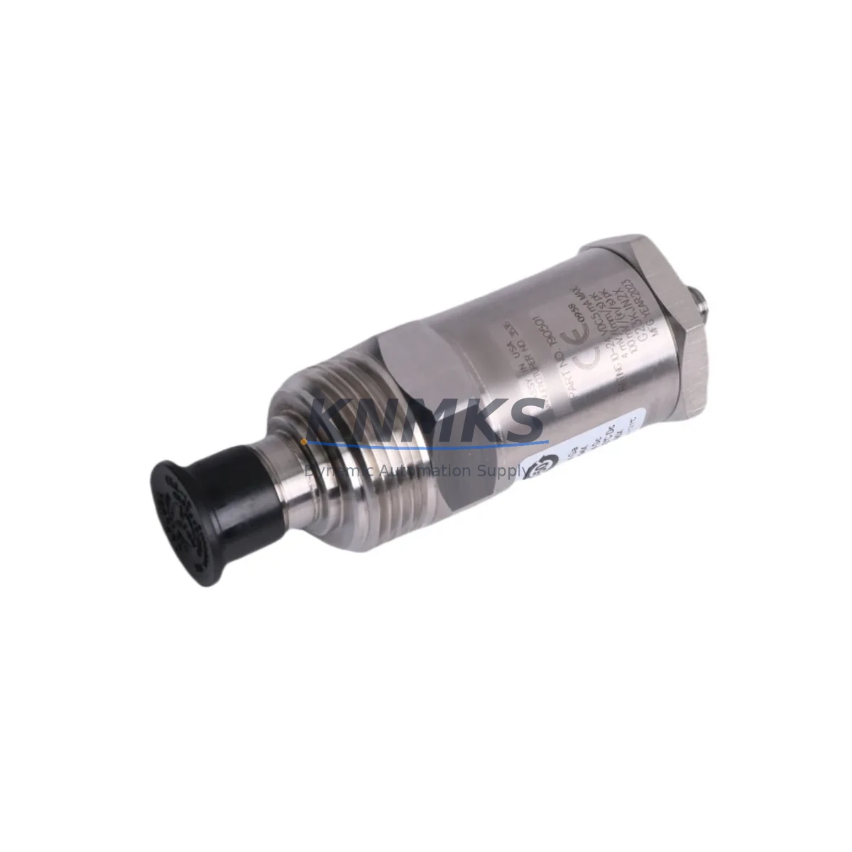
The Bently Nevada 190501-12-99-00 is a Velomitor CT piezoelectric velocity transducer engineered for continuous vibration monitoring in rotating machinery applications. As legacy 3500 Series installations age and OEM support windows close, maintenance engineers and reliability teams face increasing pressure to source tested, back-to-back compatible replacements that preserve existing wiring, rack architecture, and program logic without triggering a full system overhaul. This migration-ready unit is stocked, tested, and shipped with a support terms confirmed by quotation to support planned and emergency retrofit scenarios across petrochemical, power generation, compressor, and turbine control environments.
The 190501-12-99-00 outputs a velocity signal via a 4-pin MIL-C-5015 style connector and is designed for direct installation into existing Bently Nevada 3500 Series monitoring racks without modification to the rack backplane or I/O wiring. Engineers replacing discontinued Velomitor CT units can retain the existing Bently Nevada 3500/20 Rack Interface Module and associated 3500/42M Proximitor/Seismic Monitor cards, eliminating the need to re-engineer the monitoring channel or reconfigure alarm setpoints in the System 1 software environment. This significantly reduces commissioning time and minimizes the risk of introducing configuration errors during the replacement window.
Before proceeding with installation, retrofit planners should verify the following parameters against the existing system documentation: supply voltage compatibility (typically +24 VDC from the rack power supply), cable run length and signal attenuation characteristics, connector pin-out alignment with the existing field wiring harness, and the transducer mounting thread specification (typically 10-32 UNF or M6 depending on the machine adapter). Confirming these details against the original Bently Nevada installation drawing prevents wiring rework and avoids delays during the commissioning phase.
Migration Compatibility Table
| Parameter | 190501-12-99-00 Specification | Retrofit Notes |
|---|---|---|
| Transducer Type | Velomitor CT Piezoelectric Velocity | Direct replacement for legacy Velomitor CT units |
| Connector Type | 4-Pin MIL-C-5015 Style | Retain existing field cable; no re-termination required |
| Supply Voltage | +18 to +30 VDC (nominal +24 VDC) | Verify rack power supply output before installation |
| Output Signal | Velocity (mV/mm/s or mV/in/s) | Confirm monitor card sensitivity setting matches transducer output |
| Rack Compatibility | Bently Nevada 3500 Series | Compatible with 3500/42M Proximitor/Seismic Monitor |
| Mounting Thread | 10-32 UNF (confirm per machine adapter) | Check existing adapter thread before ordering mounting hardware |
| Installation Space | Standard Velomitor CT footprint | No bracket modification required for like-for-like swap |
| Firmware / Software | No firmware (passive transducer) | No System 1 software reconfiguration required for direct replacement |
| Communication Protocol | Analog voltage output | No protocol migration required; signal chain remains unchanged |
| Support terms | 12 Months | Covers manufacturing defects; includes pre-shipment functional test |
Retrofit Planning for Existing Automation Systems
A successful retrofit of the 190501-12-99-00 into an operating plant environment requires a structured approach that accounts for the interdependencies between the transducer, the monitoring rack, and the broader control architecture. In a typical 3500 Series installation, the velocity transducer feeds signal data to the 3500/42M Proximitor/Seismic Monitor card, which in turn communicates alarm and trip states to the 3500/22M Transient Data Interface or directly to the plant DCS via a hardwired relay or Modbus RTU link. Maintaining signal continuity across this chain is the primary objective of any like-for-like transducer replacement.
Retrofit teams should begin by auditing the 3500/20 Rack Interface Module to confirm that the rack’s internal power bus is delivering stable +24 VDC to the transducer channel. A degraded rack power supply — particularly in installations where the 3500/15 Power Supply Module has not been replaced in over a decade — can introduce noise into the velocity signal and produce false alarm conditions after the new transducer is installed. If the power supply shows signs of ripple or voltage sag under load, replacing it concurrently with the 190501-12-99-00 is strongly recommended to avoid a second maintenance window.
Cable integrity is the next critical checkpoint. In older installations, the field cable connecting the transducer to the 3500/42M monitor card may have been routed through conduit shared with high-voltage power cables, leading to electromagnetic interference that degrades signal quality. Before installing the replacement transducer, perform an insulation resistance test on the existing cable and verify that the shield drain wire is terminated correctly at the rack end only, in accordance with Bently Nevada grounding guidelines. If the cable shows degradation, replacing it with a new shielded twisted-pair run — properly rated for the installation environment — eliminates a common source of post-retrofit nuisance trips.
For plants running System 1 Evolution software, the channel configuration for the replacement 190501-12-99-00 should be reviewed in the software database before the transducer is physically swapped. Confirm that the transducer sensitivity value, full-scale range, and alarm setpoints stored in the System 1 database match the specifications of the replacement unit. If the original transducer was a non-CT Velomitor variant with a different sensitivity, the monitor card configuration will need to be updated via the 3500 Rack Configuration Software before the new unit is energized. Failing to align these parameters is a common cause of immediate over-range alarms following transducer replacement.
In multi-channel monitoring cabinets where the 190501-12-99-00 is one of several transducers feeding a shared 3500 Series rack, the retrofit window can be used to inspect adjacent channels for signs of connector corrosion, cable chafing, or loose terminations. Companion components such as the Bently Nevada 330130 proximity probe and driver, the 3500/40M Proximitor Monitor, or a 3500/61 Temperature Monitor installed in the same rack should be visually inspected and functionally tested during the same maintenance window to maximize the value of the planned outage. This approach reduces the total number of maintenance interventions required over the asset lifecycle and supports a longer mean time between planned shutdowns.
Downtime Control During System Migration
Minimizing unplanned downtime during a transducer replacement is a primary concern for operations teams managing continuous-process equipment such as compressors, turbines, and pumps. The 190501-12-99-00 is stocked and available for same-week dispatch, which supports just-in-time replacement strategies that avoid the extended lead times associated with ordering directly from the OEM for discontinued or allocation-constrained part numbers.
For planned maintenance windows, the recommended approach is to pre-stage the replacement transducer, verify its functional output using a portable signal simulator or calibration reference before the machine is taken offline, and prepare the installation tools and torque specifications in advance. This pre-staging process typically reduces the physical installation time to under two hours for a like-for-like swap, allowing the machine to be returned to service within a single shift.
Where the existing 3500 Series rack supports hot-swap or bypass functionality on non-critical monitoring channels, it may be possible to replace the transducer without a full machine shutdown, subject to the plant’s safety management system requirements and the specific rack configuration. In all cases, the replacement transducer should be allowed a minimum warm-up period — typically 15 to 30 minutes — before alarm setpoints are re-enabled, to allow the piezoelectric element to stabilize at operating temperature and eliminate false trip conditions during the initial energization phase.
Original program logic stored in the DCS or safety instrumented system is not affected by a transducer-level replacement, provided that the signal chain from the 3500/42M monitor card to the DCS I/O module remains unchanged. Hardwired relay outputs and Modbus register mappings are preserved, and no PLC or DCS program download is required. This is a key advantage of the like-for-like replacement approach enabled by the migration-ready 190501-12-99-00 and eliminates the need for a management of change review of the control logic in most jurisdictions.
Retrofit Support FAQ
Q1: Is the 190501-12-99-00 a direct drop-in replacement for the original Bently Nevada Velomitor CT?
Yes. The 190501-12-99-00 is designed as a back-to-back compatible replacement for the original Velomitor CT velocity transducer. It uses the same 4-pin connector, the same mounting thread, and produces a compatible velocity output signal. No modifications to the existing field cable, rack wiring, or monitor card configuration are required for a direct like-for-like swap in a standard 3500 Series installation.
Q2: What pre-shipment testing is performed on each unit?
Each 190501-12-99-00 unit undergoes functional output verification prior to shipment. The test confirms that the transducer produces a velocity signal within the specified sensitivity range when subjected to a controlled vibration input. A test record is available upon request. All units are covered by a support terms confirmed by quotation against manufacturing defects from the date of shipment.
Q3: Can this transducer be used with a Bently Nevada 3500/42M monitor card configured for proximity probe input?
No. The 3500/42M must be configured for seismic (velocity) input to accept the signal from the 190501-12-99-00. If the existing monitor card is currently configured for proximity probe input using a 330130 or similar Proximitor driver, the card configuration must be changed via the 3500 Rack Configuration Software before the velocity transducer is connected. Connecting a velocity transducer to a proximity-configured channel will produce incorrect readings and may trigger nuisance alarms.
Q4: What is the typical lead time and do you maintain stock?
The 190501-12-99-00 is maintained availability confirmed by RFQ for immediate dispatch. Standard orders are processed and shipped within 3–5 business days. For urgent replacement requirements, expedited shipping options are available. Contact admin@knmks.com or call +86 18359268345 to confirm current stock availability and arrange priority dispatch.
© 2026 KNMKS. All rights reserved.
Original Source: https://knmks.com
Contact: admin@knmks.com | +86 18359268345
Product Identification
- Brand / Ecosystem
-
Bently Nevada
Bently Nevada - Model / Series
-
190501-12-99-00
3500 Series - Product Family
- Sensors
- Availability Status
- Available on request after model and quantity confirmation
- Inquiry Type
- B2B RFQ, replacement inquiry and project spare-part request
- Pre-Quote Check
- Exact SKU, brand, series, quantity, nameplate photos and destination country are checked before quotation
System Path
Where this product fits in the KNMKS automation structure.
Specification & Inquiry Focus
- Sensor range
- Photoelectric, proximity and process sensors
- Common needs
- Output type, distance and connector
- Project support
- Machine detection and replacement inquiry
Buyer Confirmation
Information KNMKS checks before replying.
- Exact model
- 190501-12-99-00
- Brand / ecosystem
- Bently Nevada
- Product family
- Sensors
- Application note
- Replacement, maintenance, project build or spare-part list
- Useful photos
- Nameplate, installed unit, cabinet layout or connector side
- Delivery details
- Quantity, destination country and target schedule
Document Support
Files and notes can be confirmed during quotation.
- Product photos or nameplate confirmation when available
- Packing and delivery notes before quotation confirmation
- Support scope and delivery terms confirmed per inquiry
- Export document coordination for qualified B2B requests
Inquiry Support
- NPN/PNP, analog and digital output checking
- Connector and cable compatibility review
- Fast inquiry support for maintenance teams
What to Send Us
- Brand and exact model number: Bently Nevada 190501-12-99-00
- Quantity and required delivery time
- Application, replacement requirement or nameplate photo
- Destination country and shipping preference
RFQ Preparation
This is a product inquiry page built for RFQ communication.
Fast Model Check
Send this model to KNMKS for confirmation.
Include quantity, destination country and photos if this is a maintenance replacement. The inquiry will be saved with a reference number after submission.
Brand & Compatibility Note
KNMKS displays automation product information for well-known industrial brand ecosystems and compatible replacement references. Brand names are used for product identification and compatibility reference only; final availability and commercial terms are confirmed per quotation.
 Manufacturing
 Machine Tools
 Packaging
 Energy & Power

 PLCs & Controllers
 HMI & Displays
 Servo Systems
 Variable Frequency Drives