
Overview
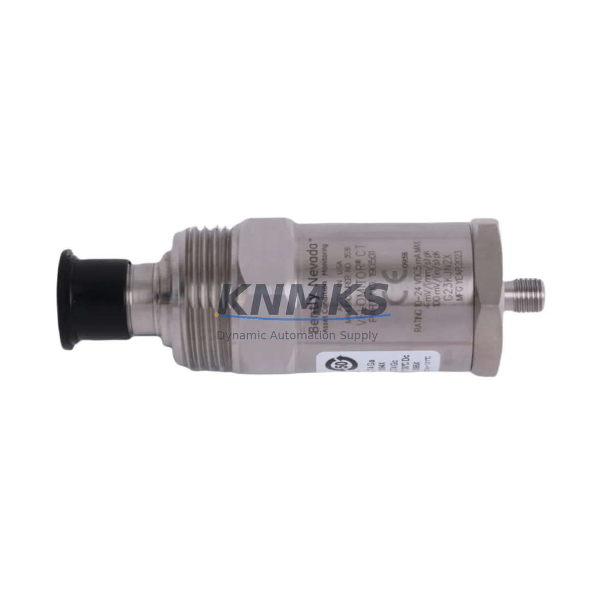
Bently Nevada 190501-12-00-04 Migration-Ready Seismic Velocity Transducer for Legacy Control Systems
The Bently Nevada 190501-12-00-04 is a Velomitor CT piezoelectric velocity transducer engineered for continuous vibration monitoring in rotating machinery protection systems. As a migration-ready replacement for aging or discontinued Velomitor units, this module integrates directly into existing Bently Nevada 3500 Series monitoring racks without requiring rack reconfiguration, rewiring of terminal blocks, or changes to the host DCS or SCADA alarm logic. For maintenance engineers managing legacy turbine, compressor, or pump protection systems, the 190501-12-00-04 represents a low-risk, high-confidence retrofit path that preserves original program logic and minimizes planned downtime windows.
The transducer delivers a 4–20 mA velocity output signal compatible with the 3500/42M Proximitor/Seismic Monitor and 3500/44M TMR Velocity Monitor input channels. Its integrated signal conditioning eliminates the need for external signal conditioners or isolators in most retrofit scenarios, reducing panel space requirements and simplifying the I/O mapping process during system migration. The M12 connector interface and 10–32 UNF mounting thread match the original Velomitor CT footprint, enabling direct mechanical substitution in existing sensor brackets and conduit runs.
Migration Compatibility Table
| Parameter | 190501-12-00-04 (This Unit) | Legacy Velomitor CT Reference |
|---|---|---|
| Output Signal | 4–20 mA velocity | 4–20 mA velocity |
| Frequency Range | 2–1000 Hz | 2–1000 Hz |
| Supply Voltage | 18–30 VDC (loop-powered) | 18–30 VDC (loop-powered) |
| Mounting Thread | 10–32 UNF | 10–32 UNF |
| Connector | M12 (4-pin) | M12 (4-pin) |
| Cable Length | 12 ft (3.66 m) | 12 ft (3.66 m) |
| Compatible Monitor | 3500/42M, 3500/44M TMR | 3500/42M, 3500/44M TMR |
| Rack Compatibility | 3500 Series backplane | 3500 Series backplane |
| Installation Space | Standard Velomitor CT envelope | Standard Velomitor CT envelope |
| Retrofit Action Required | Direct drop-in; no rewiring | — |
| Firmware/Configuration | No firmware update required | — |
| Commissioning | Loop check + alarm setpoint verify | — |
| Support terms | 12 Months | — |
Retrofit Planning for Existing Automation Systems
A successful retrofit of the 190501-12-00-04 into an operating machinery protection system begins with a thorough review of the existing 3500 Series rack configuration. Engineers should confirm the slot assignment of the 3500/42M Proximitor/Seismic Monitor or 3500/44M TMR Velocity Monitor that will receive the transducer signal, and verify that the channel’s full-scale range and alarm setpoints in the rack configuration software (System 1 or Rack Configuration Software) match the velocity sensitivity of the replacement unit.
Terminal block wiring at the I/O module interface should be documented before removal of the legacy sensor. The 190501-12-00-04 uses a standard two-wire loop-powered connection; confirm that the existing field cable pair is intact and that shield grounding follows Bently Nevada’s single-point grounding practice to avoid ground loop interference on the 4–20 mA signal. Where cable runs exceed recommended lengths or pass through high-EMI environments, a signal isolator such as the MTL5041 or equivalent DIN-rail isolator may be inserted at the marshalling cabinet without affecting the monitor’s input impedance requirements.
For systems where the 3500 rack also hosts a 3500/20 Rack Interface Module (RIM) communicating to a DCS via Modbus TCP or OPC-DA, no protocol reconfiguration is required after sensor substitution — the monitor channel tag, engineering unit scaling, and alarm logic remain unchanged. If the plant’s SCADA or DCS historian (such as an Emerson DeltaV SIS or Honeywell Safety Manager node) is configured to trend the velocity channel, verify that the historian tag mapping references the correct rack slot and channel number before returning the loop to service.
Where the retrofit is part of a broader control cabinet upgrade — for example, replacing an aging 3300 Series rack with a 3500 Series rack — additional planning is required for backplane slot mapping, power supply capacity (the 3500/15 Power Supply Module should be verified for total rack load), and I/O expansion. In multi-rack configurations, the 3500/92 Communication Gateway Module handles inter-rack data exchange; confirm that the gateway firmware version supports the channel count after expansion. HMI faceplate graphics tied to the velocity channel tag should be reviewed in the operator workstation to ensure alarm annunciation and trend displays reflect the updated sensor range.
Downtime Control During System Migration
Minimizing unplanned downtime during a Velomitor CT replacement requires a structured pre-outage preparation protocol. Before the maintenance window opens, the replacement 190501-12-00-04 should be bench-tested using a portable signal simulator to confirm the 4–20 mA output tracks correctly across the 2–1000 Hz measurement range. This pre-shipment functional test, combined with our standard support terms confirmed by quotation coverage, ensures that the unit arriving on-site is ready for immediate installation.
During the outage, the recommended sequence is: (1) place the affected 3500 monitor channel in bypass mode via the rack configuration software to suppress spurious alarms during sensor swap; (2) disconnect the field cable at the M12 connector, remove the legacy transducer from its mounting bracket, and install the 190501-12-00-04 using the same 10–32 UNF thread torque specification; (3) reconnect the field cable and restore the channel from bypass; (4) perform a loop check by verifying the 4–20 mA signal at the monitor’s front-panel display or via the System 1 software live channel view; (5) confirm that alert and danger setpoints are active and that the DCS or SIS receives the correct process value before releasing the machine to operations.
For TMR (Triple Modular Redundant) configurations using the 3500/44M, the channel bypass and restoration sequence must follow the TMR voting logic documentation to avoid inadvertent protective trips. Coordinate with the control room operator to confirm that the voting configuration (2-out-of-3 or 1-out-of-3 bypass mode) is correctly set before and after the swap. The entire sensor replacement procedure, when pre-planned with the correct spare part in hand, typically completes within a 30–60 minute maintenance window, preserving production continuity and avoiding extended machinery downtime.
Retrofit Support FAQ
Q1: Is the 190501-12-00-04 a direct drop-in replacement for all Velomitor CT variants?
The 190501-12-00-04 is a direct mechanical and electrical replacement for Velomitor CT units with the same 12 ft cable length, M12 connector, and 10–32 UNF mounting configuration. Variants with different cable lengths (e.g., -06 for 6 ft or -25 for 25 ft suffixes) have different part numbers. Confirm your existing unit’s full part number before ordering to ensure cable length compatibility.
Q2: Does replacing the transducer require changes to the 3500 rack configuration or DCS tag mapping?
No. Because the 190501-12-00-04 is a like-for-like replacement with identical output signal characteristics, the 3500 monitor channel configuration, alarm setpoints, and DCS/SCADA tag mappings do not require modification. The only recommended commissioning step is a loop check to verify the live 4–20 mA reading at the monitor after installation.
Q3: What is the lead time and support terms coverage for this unit?
Units are available from stock with same-week dispatch for most regions. Each 190501-12-00-04 is covered by a support terms confirmed by quotation against manufacturing defects. Pre-shipment functional testing is performed on every unit before dispatch to confirm output signal integrity across the rated frequency range.
Q4: Can this transducer be used with non-Bently Nevada monitoring systems?
Yes. The 4–20 mA loop-powered output is a standard industrial signal compatible with any monitor or PLC analog input card that accepts a 4–20 mA velocity signal within the 18–30 VDC supply range. However, full compatibility with Bently Nevada 3500 Series system features (such as OK relay logic and rack-level diagnostics) is only guaranteed when used with the 3500/42M or 3500/44M monitor modules.
© 2026 KNMKS. All rights reserved.
Original Source: https://knmks.com
Contact: admin@knmks.com | +86 18359268345
Product Identification
- Brand / Ecosystem
-
Bently Nevada
Bently Nevada - Model / Series
-
190501-12-00-04
3500 Series - Product Family
- Sensors
- Availability Status
- Available on request after model and quantity confirmation
- Inquiry Type
- B2B RFQ, replacement inquiry and project spare-part request
- Pre-Quote Check
- Exact SKU, brand, series, quantity, nameplate photos and destination country are checked before quotation
System Path
Where this product fits in the KNMKS automation structure.
Specification & Inquiry Focus
- Sensor range
- Photoelectric, proximity and process sensors
- Common needs
- Output type, distance and connector
- Project support
- Machine detection and replacement inquiry
Buyer Confirmation
Information KNMKS checks before replying.
- Exact model
- 190501-12-00-04
- Brand / ecosystem
- Bently Nevada
- Product family
- Sensors
- Application note
- Replacement, maintenance, project build or spare-part list
- Useful photos
- Nameplate, installed unit, cabinet layout or connector side
- Delivery details
- Quantity, destination country and target schedule
Document Support
Files and notes can be confirmed during quotation.
- Product photos or nameplate confirmation when available
- Packing and delivery notes before quotation confirmation
- Support scope and delivery terms confirmed per inquiry
- Export document coordination for qualified B2B requests
Inquiry Support
- NPN/PNP, analog and digital output checking
- Connector and cable compatibility review
- Fast inquiry support for maintenance teams
What to Send Us
- Brand and exact model number: Bently Nevada 190501-12-00-04
- Quantity and required delivery time
- Application, replacement requirement or nameplate photo
- Destination country and shipping preference
RFQ Preparation
This is a product inquiry page built for RFQ communication.
Fast Model Check
Send this model to KNMKS for confirmation.
Include quantity, destination country and photos if this is a maintenance replacement. The inquiry will be saved with a reference number after submission.
Brand & Compatibility Note
KNMKS displays automation product information for well-known industrial brand ecosystems and compatible replacement references. Brand names are used for product identification and compatibility reference only; final availability and commercial terms are confirmed per quotation.
 Manufacturing
 Machine Tools
 Packaging
 Energy & Power

 PLCs & Controllers
 HMI & Displays
 Servo Systems
 Variable Frequency Drives