
Overview
Bently Nevada 190501-12-00-02 Migration-Ready Velocity Sensor: Legacy System Retrofit & Compatibility Upgrade
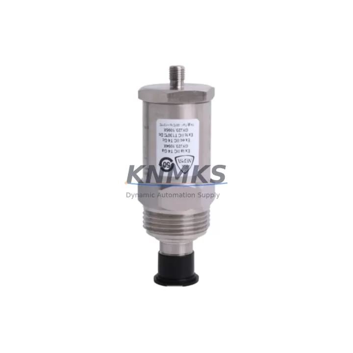
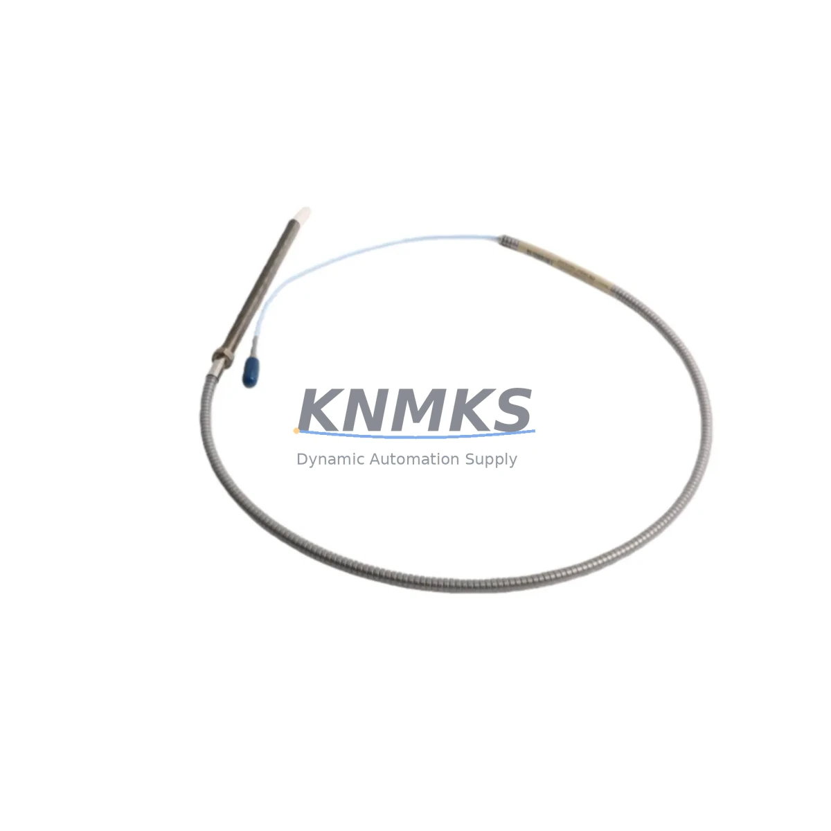
The Bently Nevada 190501-12-00-02 is a Velomitor CT piezoelectric velocity transducer engineered for direct drop-in replacement in aging vibration monitoring systems. As industrial facilities face increasing pressure to extend the operational life of their rotating machinery protection infrastructure, this module delivers a proven migration path for plants running legacy Bently Nevada 3300 Series and 3500 Series monitoring racks. Whether you are replacing a failed unit on a critical compressor train, upgrading a turbine protection panel, or consolidating spare parts inventory ahead of a planned shutdown, the 190501-12-00-02 provides the electrical and mechanical compatibility required to minimize engineering rework and reduce commissioning risk.
Migration Compatibility Table
| Parameter | 190501-12-00-02 Specification | Retrofit Notes |
|---|---|---|
| Sensor Type | Velomitor CT Piezoelectric Velocity | Direct replacement for earlier Velomitor XA and standard Velomitor models in most installations |
| Output Signal | 4–20 mA / Voltage (ICP compatible) | Verify monitor input card type: 3300/16 and 3500/42M cards accept this signal without rewiring |
| Connector / Termination | 2-pin MIL-C-5015 style connector | Confirm existing field cable connector pinout before installation; adapter cables available for older wiring harnesses |
| Mounting Interface | 1/4-28 UNF threaded stud | Check bearing housing boss thread condition; re-tap if corroded to ensure proper torque and grounding |
| Operating Temperature | -55°C to +121°C | Suitable for most turbine, compressor, and pump bearing locations without additional thermal protection |
| Communication / Protocol | Analog (4–20 mA); no fieldbus dependency | No protocol migration required; integrates directly with existing 3300/3500 rack I/O without firmware changes |
| Rack / Backplane Compatibility | 3300 Series, 3500 Series monitoring racks | Confirm rack slot assignment and channel address in System 1 or Rack Configuration Software before hot-swap |
| Installation Space | Standard Velomitor CT body dimensions | Verify clearance at bearing housing; no bracket modification required for standard installations |
| Firmware / Software | No embedded firmware (passive transducer) | No firmware update required; monitor card configuration parameters remain unchanged |
| Support terms | 12 Months | Covered from date of shipment; includes functional verification and factory test documentation |
Retrofit Planning for Existing Automation Systems
Successful integration of the 190501-12-00-02 into an existing machinery protection system requires a structured pre-installation review. Begin by auditing the target 3500 Series rack to confirm available channel capacity and verify that the 3500/42M Velocity Monitor card is configured for the correct full-scale range and alarm setpoints that match your process requirements. If the rack is operating near its I/O capacity, a 3500/20 Rack Interface Module inspection is recommended to confirm communication link integrity with the host DCS or safety system before the transducer swap.
For plants running older 3300 Series panels, the 3300/16 Dual Velocity Monitor remains a common pairing with the 190501-12-00-02. Technicians should pull the existing channel configuration from the Rack Configuration Software archive and document all alarm, danger, and time-delay setpoints before removing the legacy sensor. This protects against accidental setpoint loss during the replacement window and allows rapid restoration if the new unit requires re-ranging.
Field wiring should be inspected at the junction box and at the monitor card terminal block. Shielded twisted-pair cable with drain wire grounded at the monitor end only is the standard practice for Velomitor CT installations; confirm that no intermediate ground connections exist along the cable run, as ground loops are a leading cause of elevated noise floors and spurious alarms after transducer replacement. Where cable runs exceed recommended lengths, a signal conditioning barrier or in-line impedance matching device may be required to maintain signal integrity.
If the retrofit scope includes simultaneous replacement of proximity probe systems on the same shaft, coordinate the 190501-12-00-02 installation with the 3300/65 Keyphasor Module timing reference to ensure phase angle references remain valid after the outage. Plants upgrading from eddy-current proximity systems to velocity-based measurement on axial positions should also review the 3500/45 Position Monitor configuration to avoid channel conflicts during the transition period.
For control cabinets undergoing broader modernization — including replacement of legacy power supplies feeding the monitoring rack — verify that the 3500 rack’s internal DC bus voltage remains within specification throughout the transducer installation. A temporary UPS or rack power redundancy check using the 3500/15 Power Supply Module status indicators is recommended before breaking any field connections.
Downtime Control During System Migration
Minimizing unplanned downtime during a transducer replacement on a running plant requires pre-staging all materials and completing a full pre-work checklist before the maintenance window opens. The 190501-12-00-02 should be bench-tested against a calibrated signal source prior to installation to confirm output linearity and sensitivity within the manufacturer’s tolerance band. This pre-shipment functional verification, combined with the included factory test documentation, allows the site team to proceed with confidence and eliminates the risk of discovering a defective unit after the machine is already offline.
Where process conditions permit a hot-swap approach — common in 3500 Series racks with redundant channel configurations — the replacement sequence should be coordinated with the control room operator to temporarily suppress the affected channel alarm outputs in the DCS or safety instrumented system. Document the suppression start and end times in the management of change log and restore all alarm functions immediately after the new transducer is confirmed in service. Avoid leaving alarm suppression active beyond the minimum required window to maintain machinery protection coverage.
Original program logic in the host PLC or DCS should not require modification for a like-for-like transducer replacement, provided the new unit’s sensitivity and output range match the replaced sensor’s configuration. If the 190501-12-00-02 is being used to replace a different Velomitor model with a non-standard sensitivity factor, update the monitor card’s engineering unit scaling parameter in the Rack Configuration Software and perform a bump test to verify the end-to-end signal chain before returning the machine to service. Retain a copy of the pre- and post-change configuration files in the plant’s document management system to support future audits and regulatory compliance reviews.
Retrofit Support FAQ
Q1: Is the 190501-12-00-02 a direct replacement for the original Velomitor XA and earlier Velomitor CT variants?
In the majority of 3300 and 3500 Series installations, yes. The 190501-12-00-02 shares the same connector type, mounting thread, and output signal characteristics as the standard Velomitor CT family. However, always cross-reference the existing monitor card input specification and the original sensor’s sensitivity value before finalizing the replacement order to confirm full compatibility with your specific rack configuration.
Q2: What wiring checks are required before installing the replacement transducer?
Inspect the field cable for insulation damage, verify shield continuity, and confirm that the drain wire is grounded only at the monitor card terminal block. Check connector pin assignments against the 190501-12-00-02 wiring diagram and compare with the existing installation drawing. Replace any corroded or damaged connectors before installing the new sensor to avoid intermittent signal faults after commissioning.
Q3: How is the unit tested before shipment, and what documentation is included?
Each 190501-12-00-02 unit undergoes functional verification against calibrated test equipment prior to shipment. A factory test report confirming sensitivity, frequency response, and output linearity is included with the unit. This documentation supports incoming inspection requirements and provides a baseline reference for future condition monitoring trend analysis.
Q4: What are the inventory availability and support terms terms?
Units are maintained availability confirmed by RFQ for prompt dispatch. Standard lead time for in-stock units is 1–3 business days. Each unit is covered by a support terms confirmed by quotation from the date of shipment, covering manufacturing defects and functional failures under normal operating conditions. For volume orders or urgent requirements, contact the sales team directly to confirm current stock levels and expedited shipping options.
© 2026 KNMKS. All rights reserved.
Original Source: https://knmks.com
Contact: admin@knmks.com | +86 18359268345
Product Identification
- Brand / Ecosystem
-
Bently Nevada
Bently Nevada - Model / Series
-
190501-12-00-02
3500 Series - Product Family
- Sensors
- Availability Status
- Available on request after model and quantity confirmation
- Inquiry Type
- B2B RFQ, replacement inquiry and project spare-part request
- Pre-Quote Check
- Exact SKU, brand, series, quantity, nameplate photos and destination country are checked before quotation
System Path
Where this product fits in the KNMKS automation structure.
Specification & Inquiry Focus
- Sensor range
- Photoelectric, proximity and process sensors
- Common needs
- Output type, distance and connector
- Project support
- Machine detection and replacement inquiry
Buyer Confirmation
Information KNMKS checks before replying.
- Exact model
- 190501-12-00-02
- Brand / ecosystem
- Bently Nevada
- Product family
- Sensors
- Application note
- Replacement, maintenance, project build or spare-part list
- Useful photos
- Nameplate, installed unit, cabinet layout or connector side
- Delivery details
- Quantity, destination country and target schedule
Document Support
Files and notes can be confirmed during quotation.
- Product photos or nameplate confirmation when available
- Packing and delivery notes before quotation confirmation
- Support scope and delivery terms confirmed per inquiry
- Export document coordination for qualified B2B requests
Inquiry Support
- NPN/PNP, analog and digital output checking
- Connector and cable compatibility review
- Fast inquiry support for maintenance teams
What to Send Us
- Brand and exact model number: Bently Nevada 190501-12-00-02
- Quantity and required delivery time
- Application, replacement requirement or nameplate photo
- Destination country and shipping preference
RFQ Preparation
This is a product inquiry page built for RFQ communication.
Fast Model Check
Send this model to KNMKS for confirmation.
Include quantity, destination country and photos if this is a maintenance replacement. The inquiry will be saved with a reference number after submission.
Brand & Compatibility Note
KNMKS displays automation product information for well-known industrial brand ecosystems and compatible replacement references. Brand names are used for product identification and compatibility reference only; final availability and commercial terms are confirmed per quotation.
 Manufacturing
 Machine Tools
 Packaging
 Energy & Power

 PLCs & Controllers
 HMI & Displays
 Servo Systems
 Variable Frequency Drives