
Overview
Bently Nevada 190501-10-99-00 Migration-Ready Velocity Sensor for Legacy Control Systems
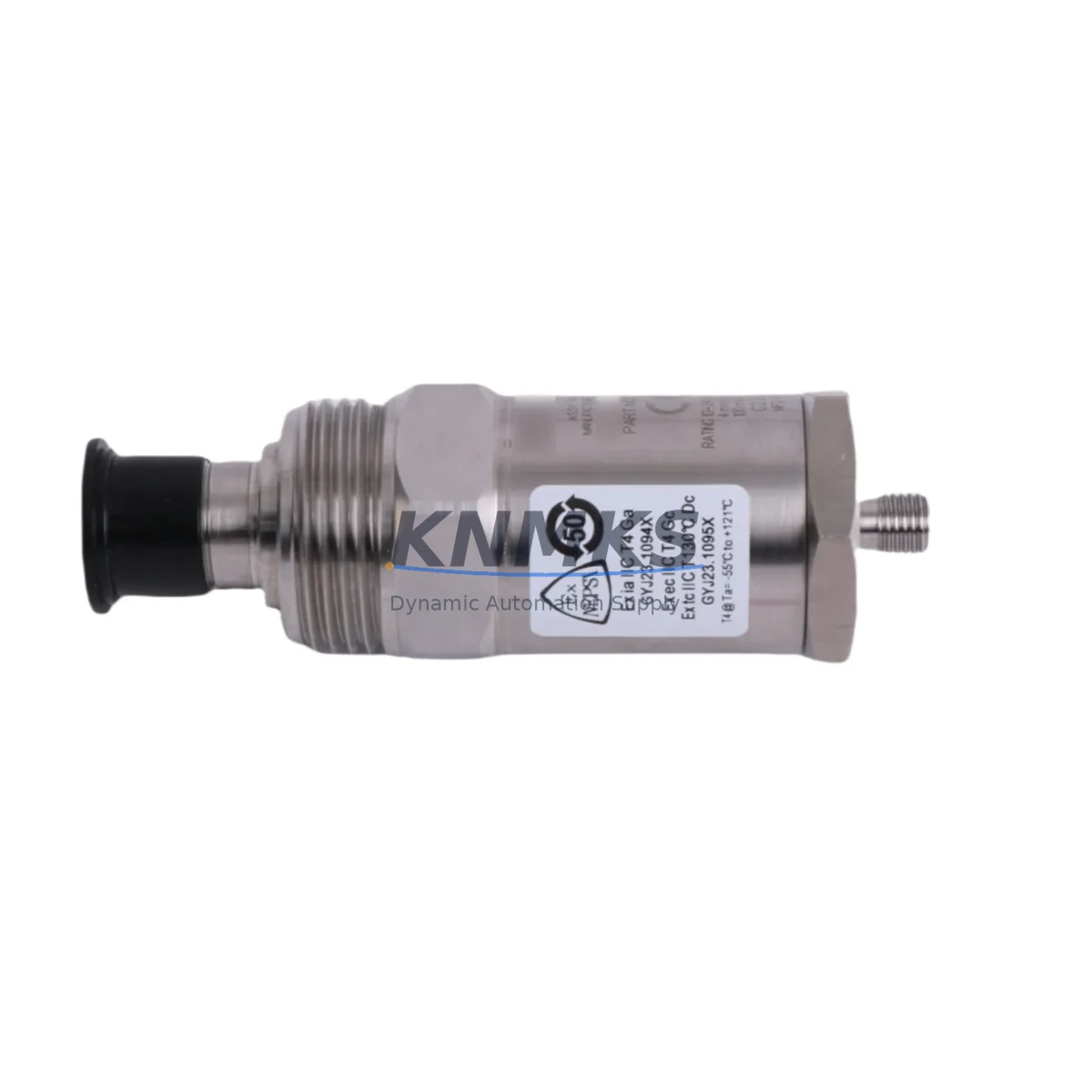
The Bently Nevada 190501-10-99-00 Velomitor CT is a high-performance velocity transducer engineered for continuous vibration monitoring in rotating machinery applications. As legacy machinery protection systems age and original Bently Nevada components approach end-of-life, the 190501-10-99-00 serves as a migration-ready replacement that preserves existing wiring infrastructure, signal conditioning architecture, and rack-level compatibility — minimizing retrofit risk and eliminating the need for full system redesign.
This unit is fully compatible with the Bently Nevada 3500 Series machinery protection rack, accepting the standard 4-20mA output signal and interfacing directly with 3500/42M and 3500/45 monitor modules without requiring additional signal converters. For plants operating legacy 7200 Series or 3300 Series monitoring systems, the 190501-10-99-00 provides a validated upgrade path that maintains measurement continuity while transitioning to a more supportable hardware baseline.
The Velomitor CT design integrates a piezoelectric sensing element with internal signal conditioning, delivering a low-impedance voltage output proportional to casing velocity. This architecture eliminates the need for external charge amplifiers and simplifies field wiring — a critical advantage when retrofitting control cabinets with limited panel space. Terminal connections follow the standard Bently Nevada two-wire configuration, and the M8 connector interface is compatible with existing field cable assemblies used across most 3500 rack installations.
During retrofit planning, engineers should verify power supply capacity at the junction box level. The 190501-10-99-00 draws from the same 18–30 VDC supply rail used by companion proximity probes and driver electronics such as the 3300 XL 8mm proximity transducer system. Where multiple transducers share a common power bus, total current draw must be recalculated to confirm the existing power module — typically a 3500/15 or 3500/05 power supply — can support the updated load without triggering undervoltage faults.
Backplane slot assignments and module addressing within the 3500 rack do not require reconfiguration when replacing a like-for-like Velomitor CT unit. However, if the retrofit involves migrating from a 7200 Series monitor to a 3500/42M vibration monitor module, the channel configuration stored in the Rack Configuration Software (RCS) must be updated to reflect the new transducer sensitivity value (100 mV/g for the 190501-10-99-00) and the correct full-scale measurement range. Failure to update these parameters will result in incorrect alarm setpoints and may trigger spurious trips during commissioning.
HMI screen updates are typically required when the tag database references legacy transducer identifiers. Operators using System 1 Evolution or third-party SCADA platforms connected via Modbus TCP or OPC-DA should confirm that the data point mapping for the affected measurement channel remains consistent after the module swap. In most cases, the channel address and engineering unit scaling are preserved, but a full loop check against the DCS historian is recommended before returning the machine to service.
Installation space confirmation is straightforward for standard 3500 rack configurations: the 190501-10-99-00 mounts directly to the machine casing using the standard 1/4-28 UNF threaded stud, and the cable routing follows the same path as the original unit. For applications where the sensor is installed in a hazardous area classified as Zone 1 or Division 1, the associated intrinsic safety barrier — such as a MTL 787S or P+F KFD2-STC4-Ex1 isolator — must be verified for compatibility with the Velomitor CT output characteristics before installation.
Firmware compatibility is not a concern for the 190501-10-99-00 itself, as it is a passive analog transducer. However, the 3500/42M monitor module firmware version should be confirmed at revision 5.0 or later to ensure full support for the transducer’s sensitivity range and to access the latest alarm configuration features available through the Rack Configuration Software.
All units supplied by KNMKS undergo pre-shipment functional testing, including output signal verification at rated supply voltage, insulation resistance check, and connector integrity inspection. Each 190501-10-99-00 is shipped with a test report and is covered by a support terms confirmed by quotation against manufacturing defects, supporting your maintenance planning and spare parts lifecycle management.
Migration Compatibility Table
| Parameter | 190501-10-99-00 (This Unit) | Legacy / Replaced Unit | Notes |
|---|---|---|---|
| Transducer Type | Velomitor CT (Velocity) | 7200 Series Velocity / 3300 XL Velocity | Direct replacement; verify sensitivity value in RCS |
| Output Signal | Low-impedance voltage (100 mV/g) | Varies by legacy model | Update channel sensitivity in 3500/42M configuration |
| Supply Voltage | 18–30 VDC | 18–30 VDC (standard) | Confirm power module capacity (3500/15 or 3500/05) |
| Connector Interface | M8, 2-wire | M8 / MIL-C-5015 (legacy) | Adapter cable may be required for MIL connector variants |
| Rack Compatibility | Bently Nevada 3500 Series | 3300, 7200 Series | 3500/42M or 3500/45 monitor module required |
| Mounting Thread | 1/4-28 UNF | 1/4-28 UNF (standard) | No mechanical modification required |
| Hazardous Area Rating | Verify per installation drawing | Zone 1 / Div 1 (with barrier) | Confirm IS barrier compatibility (MTL / P+F) |
| Commissioning Check | Loop check + RCS parameter update | N/A | Verify alarm setpoints and historian data mapping |
| Support terms | 12 Months | — | Covered from date of shipment; test report included |
Retrofit Planning for Existing Automation Systems
A successful retrofit of the 190501-10-99-00 into an existing machinery protection system requires a structured review of the surrounding hardware ecosystem. In a typical 3500 rack installation, the velocity transducer operates alongside proximity probe systems — such as the 3300 XL 8mm proximity transducer — that monitor shaft displacement on the same machine train. Both transducer types share the rack’s common power bus, so any addition or replacement of a Velomitor CT unit must be preceded by a power budget review at the 3500/15 power supply module level.
Signal routing from the field junction box to the 3500/42M monitor module typically passes through a terminal block assembly mounted in the control cabinet. When replacing the 190501-10-99-00, technicians should inspect the existing field wiring for insulation degradation, particularly in high-temperature environments where cable jackets may have hardened over years of service. If the original cable is a shielded twisted pair routed through conduit shared with power conductors, a new dedicated cable run may be required to meet the signal integrity requirements of the Velomitor CT output.
For plants that are simultaneously upgrading their communication infrastructure — for example, migrating from a legacy Modbus RTU link to Ethernet-based OPC-UA — the 3500 rack’s communication gateway module (such as the 3500/92 or 3500/93 Ethernet Interface) should be confirmed as part of the retrofit scope. This ensures that the vibration data from the newly installed 190501-10-99-00 is correctly published to the plant historian and available to the updated SCADA or DCS platform without requiring a separate data concentrator.
Where the retrofit involves expanding I/O capacity — for example, adding a new measurement point on a previously unmonitored bearing — a 3500/40M or 3500/42M monitor module may need to be added to the existing rack. In this case, the rack’s backplane slot availability must be confirmed, and the Rack Configuration Software must be updated to include the new module before the transducer is connected. The 190501-10-99-00 is fully compatible with this expansion scenario and can be commissioned on a new channel without affecting the configuration of existing channels.
For control cabinets where panel space is constrained, the compact form factor of the Velomitor CT is an advantage over older velocity transducer designs that required external charge amplifiers or signal conditioners. This is particularly relevant in retrofit projects where the original transducer was a seismic velocity pickup requiring a separate preamplifier module — replacing it with the 190501-10-99-00 can free up significant panel space and reduce the number of field terminations required.
Downtime Control During System Migration
Minimizing unplanned downtime during a velocity transducer replacement requires careful pre-staging and a clearly defined commissioning sequence. Before the maintenance window begins, the replacement 190501-10-99-00 should be bench-tested at the rated supply voltage to confirm output signal integrity, and the Rack Configuration Software should be pre-loaded with the updated channel parameters — including the correct transducer sensitivity, alarm setpoints, and danger limits — so that the configuration can be downloaded to the 3500 rack immediately after the new unit is connected.
To protect the original program logic and alarm configuration, a full backup of the existing RCS configuration file should be exported and stored before any changes are made to the rack. This backup serves as the recovery baseline if the commissioning process encounters unexpected issues and a rollback is required. For plants using System 1 Evolution for condition monitoring, the existing trend data and baseline vibration signatures should also be archived before the transducer swap, as the new unit may produce slightly different signal characteristics during the initial run-in period.
During the physical swap, the machine should be in a safe, de-energized state with the relevant monitor channel bypassed in the 3500 rack to prevent a spurious trip from an open-circuit input. Once the 190501-10-99-00 is installed and the field wiring is reconnected, the bypass should be removed and the channel should be monitored in the RCS live display to confirm that the output signal is within the expected range before the machine is restarted. A full loop check — including verification of the 4-20mA signal at the DCS input card and confirmation of the correct engineering unit display on the HMI — should be completed before the machine is returned to normal operation.
For critical applications where continuous monitoring is required, a temporary portable vibration analyzer can be used to maintain measurement coverage during the transducer swap, ensuring that any developing fault conditions are detected even while the permanent monitoring channel is offline. This approach is particularly valuable for machines with short fault progression times, such as high-speed compressors or turbines, where even a brief monitoring gap could result in a missed alarm.
Retrofit Support FAQ
Q1: Is the 190501-10-99-00 a direct drop-in replacement for the legacy Bently Nevada 7200 Series velocity transducer?
The 190501-10-99-00 Velomitor CT is functionally compatible with 7200 Series monitoring applications when used with a 3500/42M monitor module. The key difference is the output signal type: the Velomitor CT produces a low-impedance voltage output, while some 7200 Series velocity transducers used a high-impedance charge output. The 3500/42M is designed to accept the Velomitor CT output directly, but the channel configuration in the Rack Configuration Software must be updated to reflect the correct transducer type and sensitivity value before commissioning.
Q2: What wiring changes are required when installing the 190501-10-99-00 in an existing control cabinet?
In most cases, the existing two-wire shielded cable can be reused if it is in good condition and routed away from high-voltage power conductors. The M8 connector on the 190501-10-99-00 is compatible with standard Bently Nevada field cable assemblies. If the original transducer used a MIL-C-5015 connector, an adapter cable will be required. Terminal block connections at the junction box and the 3500 rack I/O module should be inspected and re-torqued during the replacement to ensure reliable signal continuity.
Q3: How is the 190501-10-99-00 tested before shipment, and what documentation is provided?
Each unit undergoes pre-shipment functional testing including output signal verification at rated supply voltage (24 VDC nominal), insulation resistance measurement, and connector integrity inspection. A test report is included with each shipment. Units are covered by a support terms confirmed by quotation from the date of shipment against manufacturing defects, supporting spare parts lifecycle planning and maintenance budget forecasting.
Q4: What is the typical lead time, and do you maintain stock for the 190501-10-99-00?
KNMKS maintains regional inventory of the 190501-10-99-00 to support urgent replacement requirements. Standard in-stock orders are processed within 1–3 business days. For blanket stock programs or scheduled maintenance outages requiring guaranteed availability, contact our sales team to discuss reserved inventory arrangements. Emergency orders for critical plant shutdowns are handled on a priority basis.
© 2026 KNMKS. All rights reserved.
Original Source: https://knmks.com
Contact: admin@knmks.com | +86 18359268345
Product Identification
- Brand / Ecosystem
-
Bently Nevada
Bently Nevada - Model / Series
-
190501-10-99-00
3500 Series - Product Family
- Sensors
- Availability Status
- Available on request after model and quantity confirmation
- Inquiry Type
- B2B RFQ, replacement inquiry and project spare-part request
- Pre-Quote Check
- Exact SKU, brand, series, quantity, nameplate photos and destination country are checked before quotation
System Path
Where this product fits in the KNMKS automation structure.
Specification & Inquiry Focus
- Sensor range
- Photoelectric, proximity and process sensors
- Common needs
- Output type, distance and connector
- Project support
- Machine detection and replacement inquiry
Buyer Confirmation
Information KNMKS checks before replying.
- Exact model
- 190501-10-99-00
- Brand / ecosystem
- Bently Nevada
- Product family
- Sensors
- Application note
- Replacement, maintenance, project build or spare-part list
- Useful photos
- Nameplate, installed unit, cabinet layout or connector side
- Delivery details
- Quantity, destination country and target schedule
Document Support
Files and notes can be confirmed during quotation.
- Product photos or nameplate confirmation when available
- Packing and delivery notes before quotation confirmation
- Support scope and delivery terms confirmed per inquiry
- Export document coordination for qualified B2B requests
Inquiry Support
- NPN/PNP, analog and digital output checking
- Connector and cable compatibility review
- Fast inquiry support for maintenance teams
What to Send Us
- Brand and exact model number: Bently Nevada 190501-10-99-00
- Quantity and required delivery time
- Application, replacement requirement or nameplate photo
- Destination country and shipping preference
RFQ Preparation
This is a product inquiry page built for RFQ communication.
Fast Model Check
Send this model to KNMKS for confirmation.
Include quantity, destination country and photos if this is a maintenance replacement. The inquiry will be saved with a reference number after submission.
Brand & Compatibility Note
KNMKS displays automation product information for well-known industrial brand ecosystems and compatible replacement references. Brand names are used for product identification and compatibility reference only; final availability and commercial terms are confirmed per quotation.
 Manufacturing
 Machine Tools
 Packaging
 Energy & Power

 PLCs & Controllers
 HMI & Displays
 Servo Systems
 Variable Frequency Drives