
Overview
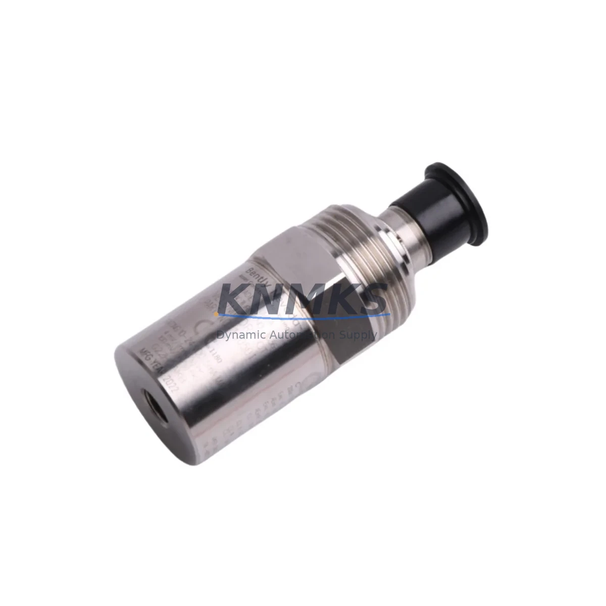
Bently Nevada 190501-05-00-04 Migration-Ready Velocity Transducer for Legacy Control Systems
The Bently Nevada 190501-05-00-04 Velomitor CT Seismic Velocity Transducer is a migration-ready, drop-in replacement engineered for industrial facilities operating legacy vibration monitoring and machinery protection systems. As rotating equipment monitoring programs transition away from discontinued sensor generations, the 190501-05-00-04 provides a verified upgrade path that preserves existing wiring infrastructure, signal conditioning architecture, and system alarm setpoints — minimizing engineering rework and unplanned downtime during retrofit campaigns.
This unit is fully compatible with Bently Nevada 3300 Series and 3500 Series monitoring racks, making it the preferred replacement for aging Velomitor and standard velocity transducer variants that have reached end-of-life or are no longer available through OEM channels. The 190501-05-00-04 delivers a broadband frequency response suitable for bearing housing, casing, and structural vibration measurement on turbines, compressors, pumps, fans, and gearboxes — the same critical asset classes where legacy sensors have historically been deployed.
Before committing to a field swap, maintenance engineers should verify the following against the existing installation: supply voltage range and current draw compatibility with the installed power supply module or barrier assembly; terminal block wiring polarity and cable shield grounding scheme at the junction box; connector type at the transducer body and at the monitor rack input card — the 190501-05-00-04 uses a standard two-pin MIL-spec connector that mates directly with most 3300 and 3500 series input modules without adapter hardware. Confirm that the rack input card, such as a 3300/16-channel velocity monitor card or a 3500/42M six-channel velocity monitor module, is configured for the correct transducer sensitivity (mV/in/s or mV/mm/s) and that alarm and danger setpoints stored in the rack configuration software reflect the new sensor’s output characteristics.
For sites running Bently Nevada System 1 condition monitoring software or interfacing with a DCS via a 3500/92 communication gateway module, no software reconfiguration is typically required when replacing a like-for-like Velomitor CT variant — the tag mapping, engineering unit scaling, and historian channel assignments remain intact. However, if the legacy sensor was a different model family, a brief System 1 database update and a rack configuration download via the 3500 Rack Configuration software should be completed and verified before returning the machine to service.
Migration Compatibility Table
| Parameter | 190501-05-00-04 (This Unit) | Legacy / Replaced Models |
|---|---|---|
| Compatible Monitor Racks | 3300 Series, 3500 Series | 3300 Series, 3500 Series |
| Connector Interface | 2-pin MIL-spec (standard) | 2-pin MIL-spec (standard) |
| Output Sensitivity | 100 mV/in/s (4 mV/mm/s) | Verify against rack card config |
| Supply Voltage | 18–30 VDC (loop powered) | Confirm barrier/power supply output |
| Frequency Response | 2–1000 Hz (±3 dB) | Verify legacy spec sheet |
| Mounting Thread | 1/4-28 UNF or M8 (confirm suffix) | Match to existing tapped hole |
| Installation Space | Standard Velomitor CT footprint | No bracket modification required |
| Communication Impact | None — rack gateway unchanged | 3500/92 gateway config preserved |
| Commissioning Requirement | Sensitivity check + alarm verify | Full loop test recommended |
| Support terms | support terms confirmed by quotation — all units shipped tested and certified | |
Retrofit Planning for Existing Automation Systems
A successful retrofit of the 190501-05-00-04 into an operating plant begins well before the maintenance window opens. The first step is a rack audit: identify the installed 3500/42M velocity monitor module or equivalent 3300-series card, confirm the channel assignment for the target machine, and export the current rack configuration file as a backup. This protects the alarm database, full-scale range settings, and OK relay logic in the event that a configuration download is required after the sensor swap.
Next, inspect the field wiring from the junction box to the rack. Most legacy Velomitor CT installations use a shielded twisted-pair cable terminated at a 3500 I/O module terminal block. Verify that the shield drain wire is grounded at one end only — typically at the rack end — to avoid ground loops that can introduce 50/60 Hz noise into the velocity signal. If the existing cable run exceeds 300 meters, check the cable capacitance specification against the 190501-05-00-04 drive capability to confirm signal integrity at the rack input.
For facilities that also operate a Bently Nevada 3500/20 power supply module or a dedicated Zener barrier assembly to provide intrinsically safe power to the transducer loop, confirm that the barrier’s maximum output current and voltage are within the 190501-05-00-04 operating envelope before energizing the loop. In hazardous area installations, the entity parameters of the new sensor must be verified against the barrier’s entity parameters and documented in the site’s hazardous area equipment register.
Where the machinery protection system feeds a DCS — for example, a Honeywell Experion PKS or an Emerson DeltaV system — via a 3500/92 Modbus or Ethernet gateway module, the channel data mapping and scaling factors in the DCS I/O configuration should be reviewed. In most like-for-like replacements the DCS tag values will track correctly without modification, but a live comparison of the DCS trend display against the rack front-panel reading during the post-installation loop test is good practice. If the site also uses a Bently Nevada TDXnet or System 1 historian, verify that the data channel remains active and that no gap in the trend record is introduced by the sensor swap.
Finally, if the retrofit scope extends beyond a single sensor to include replacement of a 3500/42M monitor module or a 3300/16-channel card alongside the transducer, plan the rack power-down sequence carefully. The 3500 rack uses a hot-swap architecture for most module types, but velocity monitor modules may require a rack power cycle to re-initialize the OK relay chain. Coordinate with the control room to place the affected machine protection channel in bypass mode in the DCS before pulling the module, and restore the bypass only after the loop test confirms correct operation.
Downtime Control During System Migration
Minimizing production impact during a velocity transducer replacement requires a structured pre-outage preparation protocol. All configuration backups, spare parts staging, and wiring verification should be completed during normal operation so that the actual maintenance window is limited to the physical swap, loop test, and alarm reinstatement — typically achievable within two to four hours for a single-channel replacement.
To protect the original program logic and alarm database, export the 3500 rack configuration file and store it on a secure engineering workstation before the outage begins. If the site uses System 1 software, create a snapshot of the machine database. These backups ensure that if a configuration download is required — for example, to update the transducer sensitivity value — the restored configuration is identical to the pre-outage baseline, with no unintended changes to other channels or machine trains.
During the swap, place the affected channel in bypass or inhibit mode at the rack and notify the DCS operator to suppress the associated alarm in the Honeywell Experion or Emerson DeltaV console. This prevents a spurious machine trip or a nuisance alarm during the period when the transducer loop is open. Once the 190501-05-00-04 is installed and the wiring is reconnected, perform a static loop check — confirm the OK LED on the 3500/42M module illuminates and that the rack front-panel reading is within the expected ambient vibration range for the stopped or idling machine.
Before releasing the machine to operations, conduct a dynamic verification: bring the machine to normal operating speed and compare the velocity reading on the rack display against a portable reference instrument if available. Confirm that the alarm and danger setpoints activate correctly by simulating a high-vibration condition using the rack’s built-in test function. Remove the bypass, restore the DCS alarm, and document the completed loop test in the site maintenance management system. This structured approach consistently delivers single-shift completion times and eliminates the risk of returning a machine to service with an unverified protection channel.
Retrofit Support FAQ
Q: Is the 190501-05-00-04 a direct drop-in replacement for other Velomitor CT variants?
A: Yes, for most standard Velomitor CT configurations installed in 3300 and 3500 series racks. Confirm the connector suffix, sensitivity rating, and mounting thread specification against your existing installation before ordering. Our technical team can cross-reference your legacy part number to confirm compatibility.
Q: What commissioning steps are required after installation?
A: Perform a static loop check to confirm the OK relay status on the monitor module, then conduct a dynamic verification at operating speed. Compare the rack reading against a reference instrument and test alarm setpoint activation using the rack’s built-in test function. Document the loop test results in your CMMS before removing the channel bypass.
Q: How is the unit tested before shipment?
A: Every 190501-05-00-04 unit is bench-tested for sensitivity, frequency response, and output linearity prior to shipment. A test certificate is available on request. Units are shipped in anti-static packaging with connector protection caps to prevent transit damage.
Q: What support terms and stock availability can I expect?
A: All units carry a support terms confirmed by quotation covering manufacturing defects and performance deviations from published specifications. We maintain regional inventory to support urgent replacement requirements, with same-day or next-business-day dispatch available for in-stock units. Contact our team for lead time confirmation on your specific quantity requirement.
© 2026 KNMKS. All rights reserved.
Original Source: https://knmks.com
Contact: admin@knmks.com | +86 18359268345
Product Identification
- Brand / Ecosystem
-
Bently Nevada
Bently Nevada - Model / Series
-
190501-05-00-04
3500 Series - Product Family
- Sensors
- Availability Status
- Available on request after model and quantity confirmation
- Inquiry Type
- B2B RFQ, replacement inquiry and project spare-part request
- Pre-Quote Check
- Exact SKU, brand, series, quantity, nameplate photos and destination country are checked before quotation
System Path
Where this product fits in the KNMKS automation structure.
Specification & Inquiry Focus
- Sensor range
- Photoelectric, proximity and process sensors
- Common needs
- Output type, distance and connector
- Project support
- Machine detection and replacement inquiry
Buyer Confirmation
Information KNMKS checks before replying.
- Exact model
- 190501-05-00-04
- Brand / ecosystem
- Bently Nevada
- Product family
- Sensors
- Application note
- Replacement, maintenance, project build or spare-part list
- Useful photos
- Nameplate, installed unit, cabinet layout or connector side
- Delivery details
- Quantity, destination country and target schedule
Document Support
Files and notes can be confirmed during quotation.
- Product photos or nameplate confirmation when available
- Packing and delivery notes before quotation confirmation
- Support scope and delivery terms confirmed per inquiry
- Export document coordination for qualified B2B requests
Inquiry Support
- NPN/PNP, analog and digital output checking
- Connector and cable compatibility review
- Fast inquiry support for maintenance teams
What to Send Us
- Brand and exact model number: Bently Nevada 190501-05-00-04
- Quantity and required delivery time
- Application, replacement requirement or nameplate photo
- Destination country and shipping preference
RFQ Preparation
This is a product inquiry page built for RFQ communication.
Fast Model Check
Send this model to KNMKS for confirmation.
Include quantity, destination country and photos if this is a maintenance replacement. The inquiry will be saved with a reference number after submission.
Brand & Compatibility Note
KNMKS displays automation product information for well-known industrial brand ecosystems and compatible replacement references. Brand names are used for product identification and compatibility reference only; final availability and commercial terms are confirmed per quotation.
 Manufacturing
 Machine Tools
 Packaging
 Energy & Power

 PLCs & Controllers
 HMI & Displays
 Servo Systems
 Variable Frequency Drives