
Overview
Bently Nevada 190501-04-00-01 Maintenance-Proven Spare Part for Factory Uptime
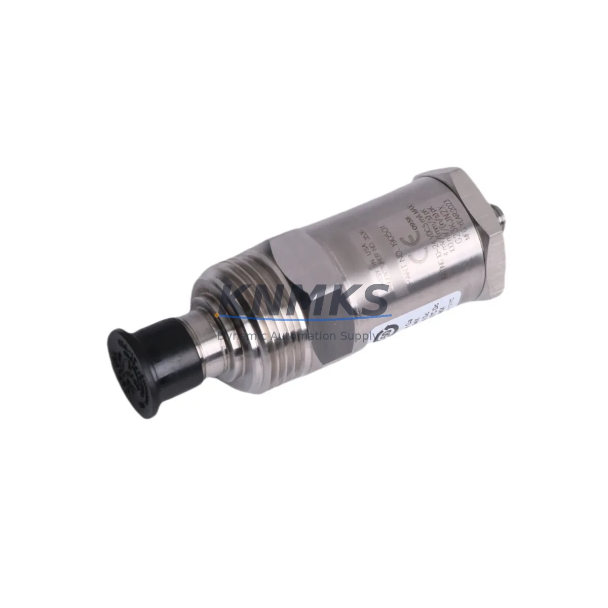
The Bently Nevada 190501-04-00-01 is a Velomitor CT piezo-velocity transducer engineered for continuous vibration monitoring in rotating machinery protection systems. Designed to integrate directly with the Bently Nevada 3500 Series machinery protection platform, this velocity transducer delivers broadband frequency response and high-sensitivity output that maintenance engineers rely on for early fault detection, bearing wear trending, and unplanned shutdown prevention. Sourced as an original spare, each unit is inspected and function-tested prior to shipment, backed by a support terms confirmed by quotation, and available from regional stock to support emergency replacement and planned annual overhaul programs.
For maintenance and procurement engineers managing rotating equipment in power generation, oil & gas, petrochemical, and heavy industrial facilities, the 190501-04-00-01 represents a critical line-replaceable unit (LRU) in the vibration monitoring loop. Its compact Velomitor CT form factor allows direct substitution for legacy seismic transducers without mechanical rework, reducing mean time to repair (MTTR) and preserving system certification continuity on 3500 Series racks.
Spare Maintenance Table
| Parameter | Specification |
|---|---|
| Part Number | 190501-04-00-01 |
| Brand | Bently Nevada |
| Series | Velomitor CT / 3500 Series |
| Product Type | Piezo-Velocity Transducer |
| Sensitivity | 100 mV/in/s (nominal) |
| Frequency Range | 2 Hz – 1,000 Hz (typical) |
| Output Signal | Voltage (IEPE / ICP compatible) |
| Supply Voltage | 18–30 VDC (constant current excitation) |
| Operating Temperature | -40°C to +121°C |
| Connector Type | 2-pin MIL-C-5015 (standard) |
| Mounting | 1/4-28 UNF stud mount |
| Compatibility | Bently Nevada 3500/42M, 3500/42E, 3500/40M velocity monitor modules |
| Application | Turbines, compressors, pumps, motors, gearboxes |
| Origin | USA |
| Condition | Original spare, function-tested |
| Support terms | 12 months from shipment date |
| Lead Time | availability confirmed by RFQ — ships within 3–5 business days |
Maintenance Planning for Continuous Operation
When scheduling replacement of the 190501-04-00-01 Velomitor CT transducer, a thorough inspection of the surrounding measurement loop is essential to avoid repeat failures and ensure signal integrity after reinstallation. Maintenance engineers should begin by verifying the condition of the Bently Nevada 3500/42M or 3500/42E velocity monitor module seated in the 3500 rack — a degraded monitor card can mask transducer faults or generate false alarms even after a new transducer is installed.
The interconnect cable assembly (typically a low-noise, shielded two-conductor cable rated for the installation environment) must be inspected for insulation breakdown, connector corrosion, and shield continuity. Cable runs exposed to high-temperature zones or mechanical vibration are particularly susceptible to intermittent faults that mimic transducer failure. Replacing the cable simultaneously with the transducer is a best practice that eliminates a common callback cause.
The 3500 rack power supply module — such as the Bently Nevada 3500/15 or 3500/20 — should be checked for output voltage stability and ripple, as constant-current excitation quality directly affects transducer sensitivity accuracy. A marginal power supply can cause measurement drift that is incorrectly attributed to the transducer itself.
For installations where the 190501-04-00-01 feeds into a 3500/32 four-channel relay module or a 3500/33 sixteen-channel relay module, relay contact condition and setpoint configuration should be verified after transducer replacement to confirm alarm and trip thresholds remain correctly calibrated. Additionally, if the 3500 rack communicates with a DCS or SCADA system via a 3500/92 communication gateway module, engineers should confirm that the Modbus or OPC data map reflects the correct channel assignment for the replaced transducer.
Where signal isolation is required between the 3500 rack output and the control room DCS input, a signal isolator or barrier (such as a Pepperl+Fuchs or MTL zener barrier for hazardous area installations) should be tested for correct attenuation and isolation resistance. Finally, the junction box terminal blocks at the field connection point should be torqued to specification and inspected for oxidation, particularly in humid or coastal environments where corrosion accelerates contact resistance degradation.
Site Replacement Workflow
Step 1 — Pre-replacement verification: Confirm the 190501-04-00-01 is the correct replacement by cross-referencing the existing transducer nameplate against the 3500 rack channel configuration in the System 1 software or the rack keypad display. Verify that the monitor module slot is configured for velocity input (not acceleration or displacement) before proceeding.
Step 2 — Safe isolation: Place the affected channel in bypass mode via the 3500 rack front panel or System 1 software to suppress spurious trip signals during the swap. Do not remove the transducer cable from the monitor module without first bypassing the channel — live disconnection can trigger a false trip on adjacent channels sharing the same power supply rail.
Step 3 — Physical replacement: Remove the legacy transducer by unscrewing the 1/4-28 UNF stud mount. Clean the mounting surface and inspect the machine casing for cracks or corrosion. Install the 190501-04-00-01 and torque to the manufacturer’s specification. Reconnect the cable assembly, ensuring the shield drain wire is terminated at one end only (typically at the monitor module end) to prevent ground loops.
Step 4 — Functional verification: Remove the channel bypass and observe the live vibration reading in System 1 or the rack display. Compare the baseline reading against historical trend data for the machine. A reading within ±10% of the pre-failure baseline confirms correct installation. If the reading is anomalous, re-inspect the cable and monitor module before concluding the transducer is faulty.
Step 5 — Documentation: Record the replacement in the CMMS (Maximo, SAP PM, or equivalent), update the spare parts inventory, and log the as-found vibration level for future trend comparison. Retain the removed transducer for failure analysis if the root cause of the original fault is unclear.
Spare Parts Support FAQ
Q1: Is the 190501-04-00-01 a direct drop-in replacement for older Velomitor transducers in the 3500 Series rack?
Yes. The 190501-04-00-01 maintains the same mechanical interface (1/4-28 UNF stud), connector pinout, and IEPE signal output as earlier Velomitor CT variants. No rack reconfiguration is required for a like-for-like swap in an existing 3500/42M or 3500/42E channel slot. Always verify the channel sensitivity setting in System 1 matches the 100 mV/in/s nominal output of this unit.
Q2: How is the unit tested before shipment?
Each 190501-04-00-01 unit undergoes a pre-shipment functional test covering output sensitivity, frequency response, and insulation resistance. Units that fail any parameter are quarantined and not shipped. A test report is available upon request for critical installations requiring documented traceability.
Q3: What is the recommended spare inventory strategy for this transducer?
For facilities operating more than four 3500 Series racks, maintaining a minimum of two 190501-04-00-01 units on-site is recommended. Given that OEM lead times for this model can extend to 8–16 weeks during allocation periods, holding buffer stock eliminates the risk of extended unmonitored operation — a condition that most machinery protection standards prohibit for critical rotating equipment.
Q4: What support terms and long-term supply support is provided?
All units are covered by a support terms confirmed by quotation from the shipment date, covering defects in materials and workmanship under normal operating conditions. For facilities requiring long-term supply agreements or blanket purchase orders to support multi-year maintenance programs, contact our sales team to discuss scheduled delivery and price-lock arrangements.
© 2026 KNMKS. All rights reserved.
Original Source: https://knmks.com
Contact: admin@knmks.com | +86 18359268345
Product Identification
- Brand / Ecosystem
-
Bently Nevada
Bently Nevada - Model / Series
-
190501-04-00-01
3500 Series - Product Family
- Sensors
- Availability Status
- Available on request after model and quantity confirmation
- Inquiry Type
- B2B RFQ, replacement inquiry and project spare-part request
- Pre-Quote Check
- Exact SKU, brand, series, quantity, nameplate photos and destination country are checked before quotation
System Path
Where this product fits in the KNMKS automation structure.
Specification & Inquiry Focus
- Sensor range
- Photoelectric, proximity and process sensors
- Common needs
- Output type, distance and connector
- Project support
- Machine detection and replacement inquiry
Buyer Confirmation
Information KNMKS checks before replying.
- Exact model
- 190501-04-00-01
- Brand / ecosystem
- Bently Nevada
- Product family
- Sensors
- Application note
- Replacement, maintenance, project build or spare-part list
- Useful photos
- Nameplate, installed unit, cabinet layout or connector side
- Delivery details
- Quantity, destination country and target schedule
Document Support
Files and notes can be confirmed during quotation.
- Product photos or nameplate confirmation when available
- Packing and delivery notes before quotation confirmation
- Support scope and delivery terms confirmed per inquiry
- Export document coordination for qualified B2B requests
Inquiry Support
- NPN/PNP, analog and digital output checking
- Connector and cable compatibility review
- Fast inquiry support for maintenance teams
What to Send Us
- Brand and exact model number: Bently Nevada 190501-04-00-01
- Quantity and required delivery time
- Application, replacement requirement or nameplate photo
- Destination country and shipping preference
RFQ Preparation
This is a product inquiry page built for RFQ communication.
Fast Model Check
Send this model to KNMKS for confirmation.
Include quantity, destination country and photos if this is a maintenance replacement. The inquiry will be saved with a reference number after submission.
Brand & Compatibility Note
KNMKS displays automation product information for well-known industrial brand ecosystems and compatible replacement references. Brand names are used for product identification and compatibility reference only; final availability and commercial terms are confirmed per quotation.
 Manufacturing
 Machine Tools
 Packaging
 Energy & Power

 PLCs & Controllers
 HMI & Displays
 Servo Systems
 Variable Frequency Drives