
Overview
Bently Nevada 190501-03-00-CN Migration-Ready Velocity Transducer for Legacy Control Systems
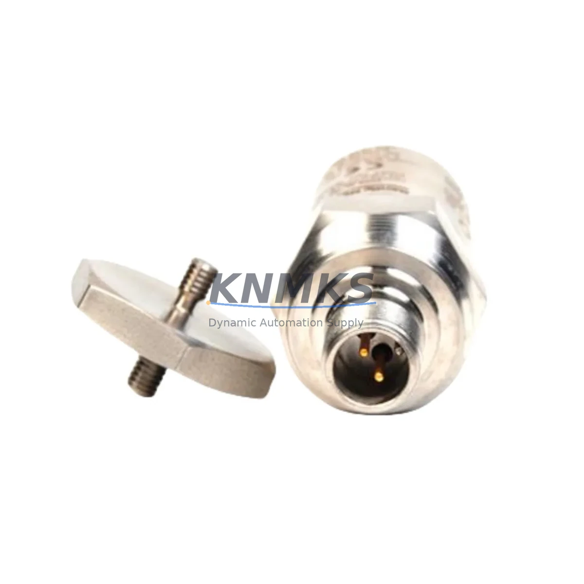
The Bently Nevada 190501-03-00-CN is a Velomitor CT piezoelectric velocity transducer engineered for seismic vibration monitoring in rotating machinery applications. As a migration-ready replacement for legacy Bently Nevada installations, this unit delivers back-to-back mechanical and electrical compatibility with existing 3500 Series monitoring racks, making it the preferred choice for maintenance engineers managing aging condition monitoring infrastructure without full system overhauls.
Facilities running legacy Bently Nevada 3500 Series systems frequently encounter discontinued transducer assemblies, degraded cable assemblies, and obsolete connector configurations that create unplanned downtime risk. The 190501-03-00-CN addresses these challenges directly: it retains the standard Velomitor CT form factor, 4–20 mA output signal range, and M12 connector pinout, allowing direct substitution without rewiring terminal blocks or reconfiguring monitor channel parameters in the 3500/42M Proximitor/Seismic Monitor or 3500/40M Proximitor/Seismic Monitor modules.
Each unit ships pre-tested against Bently Nevada factory output specifications, with full traceability documentation and a support terms confirmed by quotation covering manufacturing defects and signal integrity under normal operating conditions.
Migration Compatibility Table
| Parameter | 190501-03-00-CN (This Unit) | Legacy / OEM Reference | Migration Note |
|---|---|---|---|
| Output Signal | 4–20 mA (velocity proportional) | 4–20 mA | No channel reconfiguration required |
| Connector Type | M12, 4-pin, A-coded | M12, 4-pin, A-coded | Direct cable reuse; verify cable condition |
| Mounting Thread | 1/4-28 UNF stud mount | 1/4-28 UNF | No adapter required; confirm torque spec |
| Frequency Range | 2–1000 Hz (±3 dB) | 2–1000 Hz | Full spectral compatibility retained |
| Supply Voltage | 18–30 VDC | 18–30 VDC | Verify 3500 rack power supply output |
| Rack Compatibility | 3500/40M, 3500/42M monitor modules | 3500 Series | Confirm firmware rev on monitor module |
| Installation Space | Standard Velomitor CT envelope | Standard | No housing modification required |
| Support terms | 12 Months | Varies (OEM) | Covered from shipment date |
Retrofit Planning for Existing Automation Systems
Successful integration of the 190501-03-00-CN into an existing Bently Nevada 3500 Series installation requires a structured pre-replacement audit. Begin by confirming the power supply capacity of the 3500/01 Power Supply module — the Velomitor CT draws a nominal loop current that must remain within the rack’s aggregate channel budget, particularly in high-density installations where multiple 3500/40M or 3500/42M monitor modules share a single backplane.
Terminal block wiring should be verified against the original I/O drawing set. In installations where the existing field cable was routed through a 3500/20 Rack Interface Module or a junction box with signal isolation, confirm that the cable shield termination and drain wire routing comply with Bently Nevada’s grounding guidelines to avoid common-mode noise injection into the velocity channel. If the field cable is degraded or the connector boot is cracked, replacement with a compatible Bently Nevada field wiring assembly is recommended before commissioning the new transducer.
For systems that also include proximity probe channels — such as those using the 3500/25 Enhanced Keyphasor Module or 3500/50M Tachometer Module — verify that the Keyphasor signal reference is intact and that the phase relationship between the velocity channel and the Keyphasor pulse is preserved after transducer substitution. This is critical for machinery diagnostic software that relies on synchronous time averaging or order tracking.
Where the control system integrates Bently Nevada data into a DCS or SCADA platform via a 3500/92 Communication Gateway Module using Modbus TCP or OPC DA, no protocol reconfiguration is required following a like-for-like transducer replacement. However, if the migration also involves upgrading from a 3500 Series rack to a newer System 1 Evolution platform, the channel mapping and tag assignments in the historian must be updated to reflect the new rack address structure.
In control cabinets where space is constrained, confirm that the transducer cable bend radius and connector clearance meet the minimum requirements specified in the installation drawing. The standard Velomitor CT body length and stud mount geometry of the 190501-03-00-CN are identical to the original, so no bracket modification or cable extension is required in standard installations.
Downtime Control During System Migration
Minimizing production downtime during a Velomitor CT replacement requires pre-staging the replacement unit, verifying its output signal on the bench using a signal simulator or calibrated current source before installation, and preparing a rollback plan in case the monitor channel requires reconfiguration. In most cases, the 190501-03-00-CN can be installed and commissioned within a single planned maintenance window of two to four hours, depending on cable routing complexity and access constraints at the measurement point.
Before removing the legacy transducer, document the current alarm and danger setpoints configured in the 3500/40M or 3500/42M monitor module. These setpoints are stored in the rack configuration and are not affected by transducer substitution, but confirming them before and after replacement provides a baseline for post-installation verification. Use Bently Nevada’s System 1 or Rack Configuration Software to export the current rack configuration as a backup file before any hardware change.
After installation, perform a live signal check by observing the 4–20 mA output on the monitor module’s front-panel display or via the communication gateway. Compare the ambient vibration reading against historical baseline data to confirm the new transducer is operating within the expected range. If the reading deviates significantly, check the mounting surface condition, stud torque, and cable continuity before concluding that the transducer is faulty.
For critical machinery where continuous monitoring is mandatory, consider using a portable vibration analyzer connected in parallel during the replacement window to maintain measurement continuity and protect against undetected machinery events during the brief period when the permanent monitoring channel is offline.
Retrofit Support FAQ
Q1: Is the 190501-03-00-CN a direct drop-in replacement for the original Bently Nevada Velomitor CT?
Yes. The 190501-03-00-CN maintains the same mechanical envelope, M12 connector pinout, 4–20 mA output range, and supply voltage requirements as the original Velomitor CT. No rewiring, channel reconfiguration, or monitor module firmware update is required for a standard like-for-like replacement in a 3500 Series rack.
Q2: What pre-shipment testing is performed on each unit?
Each 190501-03-00-CN is bench-tested for output signal linearity, frequency response within the 2–1000 Hz band, supply current draw, and connector integrity before shipment. A test report is available upon request. The unit is covered by a support terms confirmed by quotation from the shipment date.
Q3: Can this transducer be used with a 3500/42M monitor module configured for proximity probe inputs?
No. The 3500/42M in proximity probe configuration expects a voltage output from an Eddy Current probe driver, not a 4–20 mA current loop. Confirm that the target monitor module slot is configured for seismic/velocity input before installation. If the slot is currently configured for proximity, a configuration change via Rack Configuration Software is required.
Q4: What is the lead time and stock availability?
The 190501-03-00-CN is maintained in regional warehouse stock to support urgent replacement requirements. Standard lead time for in-stock units is 3–7 business days for international shipments. For large-quantity blanket orders or emergency AOG requirements, contact our sales team directly to confirm allocation and expedited shipping options. All units are covered by a support terms confirmed by quotation.
© 2026 KNMKS. All rights reserved.
Original Source: https://knmks.com
Contact: admin@knmks.com | +86 18359268345
Product Identification
- Brand / Ecosystem
-
Bently Nevada
Bently Nevada - Model / Series
-
190501-03-00-CN
3500 Series - Product Family
- Sensors
- Availability Status
- Available on request after model and quantity confirmation
- Inquiry Type
- B2B RFQ, replacement inquiry and project spare-part request
- Pre-Quote Check
- Exact SKU, brand, series, quantity, nameplate photos and destination country are checked before quotation
System Path
Where this product fits in the KNMKS automation structure.
Specification & Inquiry Focus
- Sensor range
- Photoelectric, proximity and process sensors
- Common needs
- Output type, distance and connector
- Project support
- Machine detection and replacement inquiry
Buyer Confirmation
Information KNMKS checks before replying.
- Exact model
- 190501-03-00-CN
- Brand / ecosystem
- Bently Nevada
- Product family
- Sensors
- Application note
- Replacement, maintenance, project build or spare-part list
- Useful photos
- Nameplate, installed unit, cabinet layout or connector side
- Delivery details
- Quantity, destination country and target schedule
Document Support
Files and notes can be confirmed during quotation.
- Product photos or nameplate confirmation when available
- Packing and delivery notes before quotation confirmation
- Support scope and delivery terms confirmed per inquiry
- Export document coordination for qualified B2B requests
Inquiry Support
- NPN/PNP, analog and digital output checking
- Connector and cable compatibility review
- Fast inquiry support for maintenance teams
What to Send Us
- Brand and exact model number: Bently Nevada 190501-03-00-CN
- Quantity and required delivery time
- Application, replacement requirement or nameplate photo
- Destination country and shipping preference
RFQ Preparation
This is a product inquiry page built for RFQ communication.
Fast Model Check
Send this model to KNMKS for confirmation.
Include quantity, destination country and photos if this is a maintenance replacement. The inquiry will be saved with a reference number after submission.
Brand & Compatibility Note
KNMKS displays automation product information for well-known industrial brand ecosystems and compatible replacement references. Brand names are used for product identification and compatibility reference only; final availability and commercial terms are confirmed per quotation.
 Manufacturing
 Machine Tools
 Packaging
 Energy & Power

 PLCs & Controllers
 HMI & Displays
 Servo Systems
 Variable Frequency Drives