
Overview
Bently Nevada 190501-03-00-04 Migration-Ready Velocity Transducer for Legacy Control Systems
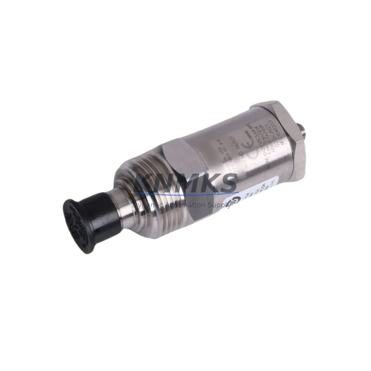
The Bently Nevada 190501-03-00-04 is a Velomitor CT piezoelectric velocity transducer engineered for direct retrofit into existing 3500 Series machinery protection systems and legacy vibration monitoring architectures. As original OEM units reach end-of-life and spare parts allocation tightens across global MRO channels, the 190501-03-00-04 provides a verified drop-in replacement path that preserves existing terminal wiring, signal conditioning chains, and 4–20 mA loop integrity without requiring panel redesign or software re-engineering.
Designed for continuous-duty applications in rotating machinery — including steam turbines, gas compressors, centrifugal pumps, and gearboxes — this transducer delivers broadband velocity measurement across the 10 Hz to 1,000 Hz frequency range. Its integral cable and MIL-spec connector interface are dimensionally compatible with the 3500/42M Velocity and Acceleration Monitor input channels, allowing maintenance teams to execute a like-for-like swap during planned outage windows without reconfiguring rack-level I/O assignments or modifying Bently Nevada System 1 historian tag mappings.
Migration Compatibility Table
| Parameter | 190501-03-00-04 (This Unit) | Legacy / Replaced Model | Retrofit Notes |
|---|---|---|---|
| Output Signal | 4–20 mA / Velocity (ICP) | 4–20 mA / Velocity (ICP) | No signal conditioning change required |
| Connector Interface | MIL-C-5015 2-pin | MIL-C-5015 2-pin | Existing field cable reusable |
| Mounting Thread | 10-32 UNF stud mount | 10-32 UNF stud mount | No bracket modification needed |
| Monitor Compatibility | 3500/42M, 3500/40M | 3500/42M, 3500/40M | Rack slot and channel address unchanged |
| Frequency Range | 10 Hz – 1,000 Hz | 10 Hz – 1,000 Hz | Alert/danger setpoints remain valid |
| Operating Temperature | -40°C to +121°C | -40°C to +121°C | No environmental re-rating required |
| Supply Voltage | 18–30 VDC (loop powered) | 18–30 VDC (loop powered) | Existing power supply capacity confirmed compatible |
| Communication Protocol | Analog 4–20 mA | Analog 4–20 mA | No protocol migration required |
| Installation Space | Standard Velomitor CT footprint | Standard Velomitor CT footprint | No panel or bracket rework |
| Support terms | support terms confirmed by quotation — covers manufacturing defects and functional failure under normal operating conditions | Applies from date of shipment | |
Retrofit Planning for Existing Automation Systems
Successful integration of the 190501-03-00-04 into a running machinery protection architecture requires a structured pre-outage review. Before scheduling the swap, maintenance engineers should pull the existing 3500 rack configuration from Bently Nevada Rack Configuration Software (RCS) and verify that the target channel on the 3500/42M Velocity and Acceleration Monitor is mapped to the correct transducer type — Velomitor CT — and that no firmware-level transducer type override has been applied at the monitor card level.
Terminal wiring at the junction box should be photographed and documented before disconnection. The 190501-03-00-04 uses a standard 2-conductor shielded cable run, and the shield drain wire termination point at the 3500/20 Rack Interface Module must be confirmed to be grounded at one end only to avoid ground loop interference on the velocity signal. If the existing cable run exceeds 300 meters, verify that the loop resistance budget remains within the monitor’s input impedance specification before reusing the original cable.
For sites running a 3500/22M Transient Data Interface alongside the standard protection rack, confirm that the transient capture configuration references the correct channel tag. Transient data historian entries in System 1 software will need a tag validation pass after the physical swap to ensure waveform capture is attributed to the correct machine train position — typically radial bearing locations on the drive-end and non-drive-end of the monitored machine.
Where the control architecture integrates a 3500/32 4-Channel Relay Module for alarm and trip output, no relay setpoint reconfiguration is required provided the replacement transducer’s sensitivity and frequency response match the original specification. However, a functional trip test using a calibrated signal simulator — such as the Bently Nevada TK-3 portable calibrator — is strongly recommended before returning the machine to service, particularly on critical compressor trains where spurious trips carry significant production impact.
Sites that have migrated their DCS integration layer to a Modbus TCP or OPC-UA gateway via a third-party protocol converter should verify that the analog input scaling at the gateway has not been altered since the original transducer commissioning. A mismatch between the 4–20 mA span and the engineering unit scaling in the DCS historian can produce false trend data even when the physical transducer is functioning correctly. This is a common oversight during like-for-like transducer replacements on sites where the DCS and the machinery protection system were commissioned by different contractors.
If the site is simultaneously upgrading adjacent I/O infrastructure — for example, replacing a legacy 3500/40M Proximitor/Seismic Monitor with a current-production equivalent — coordinate the outage window to cover both replacements in a single planned shutdown. Combining transducer and monitor card replacements in one outage cycle reduces total downtime exposure and allows a single end-to-end functional verification pass covering both velocity and proximity channels before machine restart.
Downtime Control During System Migration
Minimizing unplanned downtime during a transducer replacement on a critical rotating machine requires pre-staging all replacement components, tools, and documentation before the outage window opens. The 190501-03-00-04 should be bench-tested against a known-good signal source prior to installation to confirm output linearity and connector integrity — a step that eliminates the risk of discovering a transit-damaged unit after the machine has already been taken offline.
The original program logic in the 3500 rack does not require modification for a like-for-like transducer swap. Alert and danger setpoints, time delays, and relay voting logic remain valid and should not be altered unless a formal setpoint review has been completed as part of a broader reliability improvement program. Preserving the existing logic configuration eliminates the need for a Management of Change (MOC) review in most regulated facilities, which can otherwise add days to the outage approval cycle.
To maintain field control continuity during the swap, coordinate with the control room to place the affected monitor channel in bypass mode using the 3500 rack’s front-panel bypass function or via RCS software before disconnecting the transducer. This prevents a spurious trip signal from propagating to the 3500/32 Relay Module and triggering an unintended machine shutdown during the physical replacement procedure. Restore the channel from bypass only after the replacement transducer has been connected, the cable shield verified, and a static output check completed at the monitor front panel.
Post-installation, allow a 15–30 minute warm-up period for the Velomitor CT’s internal electronics to stabilize before logging baseline vibration readings. Compare the new baseline against the pre-outage trend data in System 1 to confirm that the replacement transducer is tracking consistently with historical machine behavior. Any deviation greater than 10% of the pre-outage baseline warrants investigation before the outage is formally closed.
Retrofit Support FAQ
Q1: Is the 190501-03-00-04 a direct drop-in replacement for the original Velomitor CT without any wiring changes?
Yes. The 190501-03-00-04 maintains the same MIL-C-5015 2-pin connector, 10-32 UNF stud mount, and 4–20 mA loop-powered output as the original Velomitor CT specification. Existing field cables, junction box terminations, and monitor channel configurations are fully reusable without modification.
Q2: What pre-shipment testing is performed on each unit?
Each 190501-03-00-04 undergoes functional output verification, connector integrity inspection, and sensitivity calibration check prior to shipment. Units are shipped with a test record confirming compliance with the Velomitor CT performance specification. The support terms confirmed by quotation cover manufacturing defects and functional failure under normal operating conditions from the date of shipment.
Q3: Can this transducer be used with a 3500/40M monitor instead of the 3500/42M?
Yes. The 190501-03-00-04 is compatible with both the 3500/42M Velocity and Acceleration Monitor and the 3500/40M Proximitor/Seismic Monitor when configured for seismic (velocity) input. Confirm the monitor channel is set to Velomitor CT transducer type in RCS before installation.
Q4: What is the typical lead time and stock availability?
We maintain regional buffer stock of the 190501-03-00-04 to support urgent MRO and unplanned outage requirements. Standard in-stock orders ship within 1–3 business days. For blanket orders or multi-unit site programs, contact our sales team to discuss reserved allocation and consignment stocking arrangements.
© 2026 KNMKS. All rights reserved.
Original Source: https://knmks.com
Contact: admin@knmks.com | +86 18359268345
Product Identification
- Brand / Ecosystem
-
Bently Nevada
Bently Nevada - Model / Series
-
190501-03-00-04
3500 Series - Product Family
- Sensors
- Availability Status
- Available on request after model and quantity confirmation
- Inquiry Type
- B2B RFQ, replacement inquiry and project spare-part request
- Pre-Quote Check
- Exact SKU, brand, series, quantity, nameplate photos and destination country are checked before quotation
System Path
Where this product fits in the KNMKS automation structure.
Specification & Inquiry Focus
- Sensor range
- Photoelectric, proximity and process sensors
- Common needs
- Output type, distance and connector
- Project support
- Machine detection and replacement inquiry
Buyer Confirmation
Information KNMKS checks before replying.
- Exact model
- 190501-03-00-04
- Brand / ecosystem
- Bently Nevada
- Product family
- Sensors
- Application note
- Replacement, maintenance, project build or spare-part list
- Useful photos
- Nameplate, installed unit, cabinet layout or connector side
- Delivery details
- Quantity, destination country and target schedule
Document Support
Files and notes can be confirmed during quotation.
- Product photos or nameplate confirmation when available
- Packing and delivery notes before quotation confirmation
- Support scope and delivery terms confirmed per inquiry
- Export document coordination for qualified B2B requests
Inquiry Support
- NPN/PNP, analog and digital output checking
- Connector and cable compatibility review
- Fast inquiry support for maintenance teams
What to Send Us
- Brand and exact model number: Bently Nevada 190501-03-00-04
- Quantity and required delivery time
- Application, replacement requirement or nameplate photo
- Destination country and shipping preference
RFQ Preparation
This is a product inquiry page built for RFQ communication.
Fast Model Check
Send this model to KNMKS for confirmation.
Include quantity, destination country and photos if this is a maintenance replacement. The inquiry will be saved with a reference number after submission.
Brand & Compatibility Note
KNMKS displays automation product information for well-known industrial brand ecosystems and compatible replacement references. Brand names are used for product identification and compatibility reference only; final availability and commercial terms are confirmed per quotation.
 Manufacturing
 Machine Tools
 Packaging
 Energy & Power

 PLCs & Controllers
 HMI & Displays
 Servo Systems
 Variable Frequency Drives