
Overview
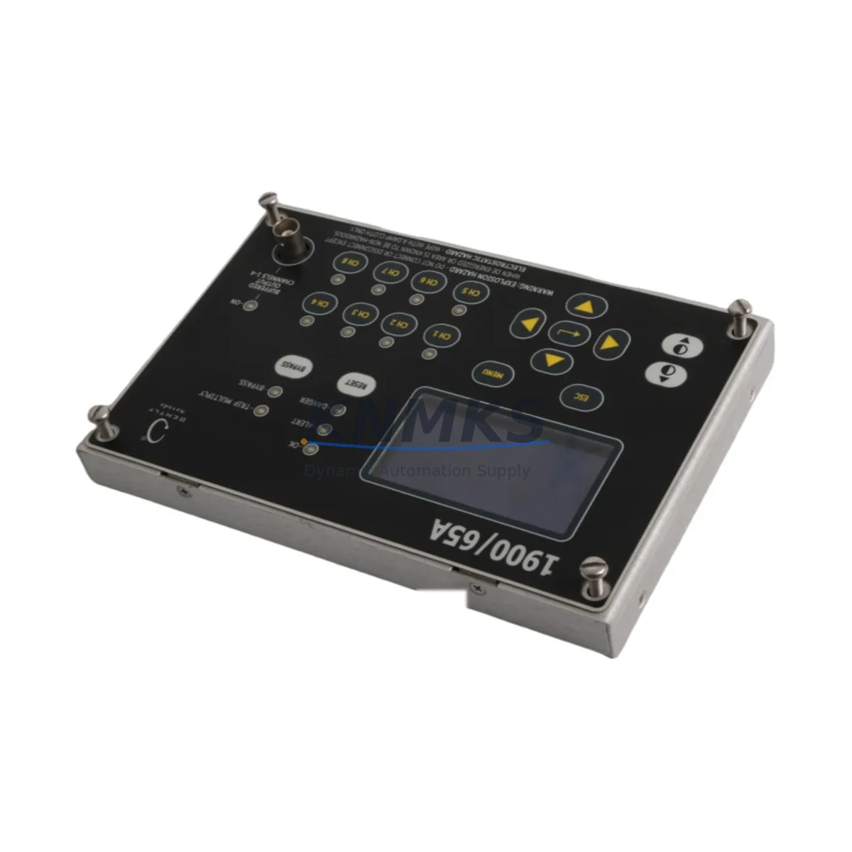
Bently Nevada 1900/65A-01-00-03-00-00 Vibration Monitor: Migration-Ready Replacement for Legacy Control Systems
The Bently Nevada 1900/65A-01-00-03-00-00 is a general-purpose vibration monitoring module widely deployed in rotating machinery protection systems across oil & gas, power generation, petrochemical, and heavy industrial facilities. As original equipment manufacturers phase out legacy 1900-series hardware and end-of-life notices become more frequent, plant engineers and reliability teams face increasing pressure to source verified replacement units that maintain full compatibility with existing wiring, rack infrastructure, and System 1 software environments.
This listing supplies migration-ready 1900/65A-01-00-03-00-00 units that have been functionally tested prior to shipment. Each module is verified against the original Bently Nevada hardware specification, covering input channel configuration, relay output logic, 4–20 mA analog output calibration, and Keyphasor input compatibility. Units are available from in-stock inventory with a support terms confirmed by quotation, supporting both emergency replacement and planned maintenance windows.
Migration Compatibility Table
| Parameter | Detail |
|---|---|
| SKU / Part Number | 1900/65A-01-00-03-00-00 |
| Brand / Manufacturer | Bently Nevada (Baker Hughes) |
| Series | 1900/65A Vibration Monitor Series |
| Module Type | General-Purpose Vibration Monitor |
| Input Channels | 2 vibration inputs (radial / axial configurable) |
| Keyphasor Input | Compatible with standard Bently Nevada Keyphasor probes |
| Analog Output | 4–20 mA (configurable per channel) |
| Relay Outputs | Alert and Danger relay outputs (configurable) |
| Rack / Backplane | Compatible with 1900-series rack backplane; verify slot addressing before installation |
| Communication Protocol | Modbus RTU / System 1 software integration |
| Power Supply Requirement | 24 VDC (verify rack PSU capacity before hot-swap) |
| Installation Form Factor | Standard 1900-series card slot; confirm physical clearance in existing cabinet |
| Firmware Compatibility | Verify System 1 software version supports module firmware revision |
| Direct Replacement For | 1900/65A variants; cross-reference full suffix before ordering |
| Retrofit Recommendation | Confirm terminal block wiring map, module address, and relay logic before power-up |
| Pre-Shipment Testing | Functional test completed; calibration report available on request |
| Support terms | 12 months from date of shipment |
| Origin | United States |
Retrofit Planning for Existing Automation Systems
Replacing a 1900/65A-01-00-03-00-00 in an operating plant requires a structured approach that accounts for the full scope of the monitoring loop — not just the module itself. Before removing the legacy unit, engineers should document the existing terminal block wiring assignments, confirm the rack backplane slot address, and capture the current alert and danger setpoints from the System 1 configuration database. Failure to record these parameters before removal is one of the most common causes of extended commissioning time during unplanned replacements.
Power supply capacity is a critical checkpoint. The 1900-series rack relies on a dedicated 24 VDC power module — often a 1900/10 or equivalent rack power supply — and adding or swapping monitoring cards without verifying available headroom can cause undervoltage conditions that affect adjacent modules. Confirm that the rack PSU can support the replacement module’s inrush and steady-state current draw before proceeding.
For facilities running Modbus RTU communication links between the 1900-series rack and a DCS or SCADA system, verify that the module address and register map remain consistent with the existing polling configuration. In some installations, the 1900/65A communicates through a 1900/20 communication gateway or a dedicated serial interface card; these intermediary components should be inspected for firmware compatibility before the replacement module is brought online.
I/O wiring adaptation is another area that demands careful attention. The 1900/65A-01-00-03-00-00 uses a standard Bently Nevada terminal block layout, but field wiring from eddy-current proximity probes — such as those in the 3300 XL or 7200 series — must be verified for correct polarity, cable shielding continuity, and driver gap voltage before the new module is energized. If the existing probe driver is a 3300 RAM or similar proximitor, confirm that the output voltage range is within the input specification of the replacement module.
HMI screen updates are frequently overlooked during module swaps. If the plant HMI — whether a Wonderware InTouch panel, a Rockwell FactoryTalk View station, or a third-party SCADA display — references specific tag names or Modbus register addresses tied to the 1900/65A channel configuration, those references must be validated after the replacement is installed. A mismatch between the HMI tag database and the new module’s register map can result in false readings or missed alarms during the post-installation verification period.
Where the retrofit involves a broader control cabinet upgrade — for example, migrating from a legacy 1900-series standalone rack to a more integrated monitoring architecture — consider the role of adjacent components such as the 3500/22M transient data interface, the 3500/42M proximitor monitor, or a 3500/15 power supply module if the facility is transitioning toward the 3500-series platform. Understanding the migration path between these platforms early in the planning process reduces the risk of incompatible backplane configurations or communication protocol conflicts during cutover.
Downtime Control During System Migration
Minimizing downtime during a 1900/65A-01-00-03-00-00 replacement begins with pre-staging the replacement module and verifying its configuration before the maintenance window opens. Where possible, pre-load the module address and configure relay setpoints on the bench using a portable System 1 configuration tool, so that the on-site installation step is limited to physical insertion, terminal block reconnection, and a final loop check.
Preserving the original program logic and alarm setpoint database is non-negotiable. Export the full System 1 configuration for the affected rack before any hardware is disturbed. This export serves as both a rollback reference and a commissioning baseline. If the replacement module requires a firmware update to match the System 1 software version running in the control room, perform that update on the bench prior to installation — never attempt a firmware update on a live rack during a production maintenance window.
For facilities where continuous vibration monitoring is a safety-critical requirement, coordinate the replacement with the operations team to ensure that the affected machine train is either taken offline or that a temporary portable vibration monitor is deployed to maintain surveillance during the swap interval. This approach protects both the equipment and the integrity of the protection system record.
After installation, conduct a structured commissioning sequence: verify probe gap voltage, confirm 4–20 mA output at a known vibration level, test relay output continuity, and validate Modbus communication with the DCS or SCADA host. Document all as-found and as-left readings. A complete commissioning record reduces audit risk and supports the support terms confirmed by quotation claim process if a defect is identified after installation.
Retrofit Support FAQ
Q1: Is the 1900/65A-01-00-03-00-00 a direct drop-in replacement for other 1900/65A suffix variants?
The 1900/65A series uses suffix codes to define channel configuration, relay output type, and communication options. The -01-00-03-00-00 suffix specifies a particular factory configuration. Before ordering, cross-reference the full suffix of the unit being replaced against this listing. If the suffix differs, contact our sales team to confirm functional equivalence or identify the correct replacement part number.
Q2: What pre-shipment testing is performed on each unit?
Each 1900/65A-01-00-03-00-00 module undergoes functional testing covering channel input response, relay output operation, analog output calibration, and power supply compatibility. A calibration report is available on request. Units are shipped with a support terms confirmed by quotation from the date of shipment, covering manufacturing defects and functional failures under normal operating conditions.
Q3: How do I verify wiring compatibility before installation?
Obtain the original Bently Nevada terminal block wiring diagram for the 1900/65A series from the system documentation package. Compare the existing field wiring — including probe cable, Keyphasor input, relay output, and 4–20 mA loop connections — against the replacement module’s terminal assignment. If the original wiring diagram is unavailable, our technical team can assist with terminal identification based on the installed rack configuration.
Q4: What is the lead time and inventory availability?
This module is available from in-stock inventory. Standard orders ship within 2–5 business days. For urgent replacement requirements, expedited shipping options are available. Contact our sales team at admin@knmks.com or +86 18359268345 to confirm current stock levels and arrange priority dispatch.
© 2026 KNMKS. All rights reserved.
Original Source: https://knmks.com
Contact: admin@knmks.com | +86 18359268345
Product Identification
- Brand / Ecosystem
-
Bently Nevada
Bently Nevada - Model / Series
- 1900/65A-01-00-03-00-00
- Product Family
- Other Components
- Availability Status
- Available on request after model and quantity confirmation
- Inquiry Type
- B2B RFQ, replacement inquiry and project spare-part request
- Pre-Quote Check
- Exact SKU, brand, series, quantity, nameplate photos and destination country are checked before quotation
System Path
Where this product fits in the KNMKS automation structure.
Specification & Inquiry Focus
- Component range
- Breakers, terminals and cabinet accessories
- Common needs
- Model, photo and installation requirement
- Project support
- Maintenance and mixed spare-part inquiry
Buyer Confirmation
Information KNMKS checks before replying.
- Exact model
- 1900/65A-01-00-03-00-00
- Brand / ecosystem
- Bently Nevada
- Product family
- Other Components
- Application note
- Replacement, maintenance, project build or spare-part list
- Useful photos
- Nameplate, installed unit, cabinet layout or connector side
- Delivery details
- Quantity, destination country and target schedule
Document Support
Files and notes can be confirmed during quotation.
- Product photos or nameplate confirmation when available
- Packing and delivery notes before quotation confirmation
- Support scope and delivery terms confirmed per inquiry
- Export document coordination for qualified B2B requests
Inquiry Support
- Mixed automation spare parts inquiry
- Cabinet component and accessory support
- Model identification from photos or labels
What to Send Us
- Brand and exact model number: Bently Nevada 1900/65A-01-00-03-00-00
- Quantity and required delivery time
- Application, replacement requirement or nameplate photo
- Destination country and shipping preference
RFQ Preparation
This is a product inquiry page built for RFQ communication.
Fast Model Check
Send this model to KNMKS for confirmation.
Include quantity, destination country and photos if this is a maintenance replacement. The inquiry will be saved with a reference number after submission.
Brand & Compatibility Note
KNMKS displays automation product information for well-known industrial brand ecosystems and compatible replacement references. Brand names are used for product identification and compatibility reference only; final availability and commercial terms are confirmed per quotation.
 Manufacturing
 Machine Tools
 Packaging
 Energy & Power
 PLCs & Controllers
 HMI & Displays
 Servo Systems
 Variable Frequency Drives