
Overview
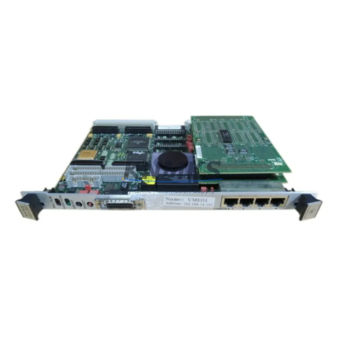
Allen-Bradley MVME162-262 Migration-Ready VMEbus Controller: Legacy System Retrofit & Compatibility Upgrade
The Allen-Bradley MVME162-262 is a VMEbus-based embedded controller from the MVME162 series, originally designed for high-reliability industrial control applications including process automation, motion control, and distributed I/O management. As legacy Rockwell Automation and Allen-Bradley VMEbus platforms approach end-of-life, the MVME162-262 remains a critical spare and direct replacement module for facilities operating aging control cabinets that cannot be immediately migrated to modern ControlLogix or CompactLogix architectures.
This unit is fully tested prior to shipment, backed by a support terms confirmed by quotation, and sourced from verified industrial supply channels. It is suitable for drop-in replacement in existing MVME162-series rack installations where downtime must be minimized and program logic must be preserved without full system re-engineering.
Migration Compatibility Table
| Parameter | MVME162-262 Specification | Retrofit / Migration Notes |
|---|---|---|
| Bus Architecture | VMEbus (IEEE 1014) | Confirm backplane slot pitch and J1/J2 connector alignment before installation |
| Processor | Motorola 68040 / 68LC040 | Verify firmware image compatibility with existing OS (VxWorks / OS-9) |
| Memory | Up to 32 MB DRAM (configuration-dependent) | Match DRAM configuration to original module; mismatched memory maps may cause boot failure |
| Serial Communication | RS-232 / RS-422 (4 channels) | Re-map COM port assignments in HMI and SCADA configurations after swap |
| Ethernet / LAN | 10BASE-T (optional, variant-dependent) | Confirm IP address and subnet settings; update ARP tables on connected devices |
| I/O Interface | VMEbus P1/P2 backplane I/O | Verify I/O module addresses and interrupt vectors match original rack configuration |
| Power Requirement | +5 VDC, ±12 VDC via VMEbus backplane | Measure backplane power rail capacity before insertion; insufficient +5V supply causes random resets |
| Physical Form Factor | 6U VMEbus single-slot | Confirm rack slot availability; adjacent modules must not obstruct airflow or connector access |
| Replacement Compatibility | Direct replacement for MVME162-2xx series variants | Cross-reference suffix codes (-262 vs -263, -264) for memory and I/O option differences |
| Support terms | support terms confirmed by quotation — All units tested prior to shipment. Defective units replaced or refunded within confirmed support period. | |
Retrofit Planning for Existing Automation Systems
Replacing the MVME162-262 in an active production environment requires a structured approach that accounts for the full control architecture — not just the CPU module itself. In most legacy VMEbus installations, the MVME162-262 operates alongside a suite of companion modules that must remain functional throughout the swap process.
Begin by auditing the VMEbus rack configuration. Document every occupied slot, including any MVME712 transition modules or MVME761 transition boards that provide rear-panel I/O connectivity. These transition modules carry the field wiring terminations and must not be disturbed during the CPU replacement. If the rack uses an MVME050 or similar interrupt handler module, verify that interrupt priority assignments are preserved in the replacement unit’s firmware configuration.
Power integrity is a frequent failure point in aging VMEbus systems. Before inserting the MVME162-262, measure the +5 VDC rail under load using a calibrated meter at the backplane connector. Many legacy VMEbus power supplies — particularly those in cabinets over 15 years old — exhibit voltage droop under full rack load. If the +5V rail reads below 4.85 V, the power supply should be replaced or supplemented before the new CPU module is installed. A failing power supply will cause the MVME162-262 to exhibit intermittent resets or fail to complete its POST sequence.
Communication link continuity is equally critical. In systems where the MVME162-262 serves as a gateway between the VMEbus backplane and upstream SCADA or DCS platforms via RS-422 serial links, the baud rate, parity, stop bits, and handshaking parameters must be documented before the swap and verified after restart. If the system includes an MVME172 or MVME177 as a secondary processor or coprocessor in the same rack, confirm that the inter-processor communication protocol (shared memory or mailbox registers) is re-initialized correctly after the CPU replacement.
For facilities that also operate Allen-Bradley SLC 500 or MicroLogix controllers in adjacent control panels, the MVME162-262 replacement should be coordinated with any DH+ or DH-485 network segment that the VMEbus system monitors or controls. Disruption to the VMEbus CPU can propagate alarms across the DH+ network if watchdog timers are not properly suspended during the maintenance window.
HMI screen updates are often overlooked during VMEbus CPU replacements. If the plant HMI — whether a legacy PanelView or a PC-based SCADA station — communicates directly with the MVME162-262 via a serial or Ethernet link, the HMI driver configuration must be verified post-swap. Tag address mappings, polling rates, and timeout values should be confirmed against the original commissioning documentation before returning the system to automatic mode.
Finally, if the retrofit scope extends beyond a single CPU swap to include I/O expansion — for example, adding MVME162-series compatible digital or analog I/O modules to increase channel count — the module base address switches must be set to non-conflicting addresses before rack power-up. Address conflicts between the MVME162-262 and newly added I/O modules are a common cause of initialization failures during post-retrofit commissioning.
Downtime Control During System Migration
Minimizing unplanned downtime during a VMEbus CPU replacement requires preparation that begins well before the maintenance window opens. The most effective strategy is to create a complete firmware and configuration backup of the existing MVME162-262 before it fails — or, if the module has already failed, to reconstruct the configuration from commissioning records, PLC program backups, and HMI tag databases.
Where possible, perform a bench test of the replacement MVME162-262 before bringing it to the plant floor. Load the firmware image, configure the serial port parameters, and verify basic POST completion in a controlled environment. This eliminates the risk of discovering a configuration issue during a live maintenance window when production pressure is highest.
During the physical swap, follow a strict sequence: power down the VMEbus rack, extract the failed module, insert the replacement, restore power, and observe the POST LED sequence before reconnecting any field communication cables. Reconnecting serial or Ethernet links before the module completes initialization can cause the remote device to latch into an error state that requires a full communication stack reset to clear.
Preserve the original ladder logic or C-language control program by maintaining an offline copy on a dedicated engineering workstation. For systems running VxWorks-based applications, ensure the boot ROM image and application binary are stored separately so that a secondary firmware failure does not result in a complete loss of the control program. If the system uses battery-backed SRAM for retentive data storage, replace the onboard battery in the new MVME162-262 before commissioning to prevent data loss during the next power cycle.
Plan the maintenance window to include a minimum 30-minute functional verification period after restart. During this period, cycle all I/O points, verify all serial communication links, confirm HMI data refresh, and check alarm annunciation before releasing the system to production operators. A structured post-swap checklist reduces the risk of latent faults being discovered during the next production shift.
Retrofit Support FAQ
Q1: Is the MVME162-262 a direct drop-in replacement for other MVME162 series variants?
The MVME162-262 is directly compatible with other MVME162-2xx series variants in terms of physical form factor and VMEbus interface. However, suffix codes indicate differences in installed DRAM capacity, optional Ethernet, and I/O configuration. Before substituting a -262 for a -263 or -264, cross-reference the original module’s option label and verify that the firmware image and memory map are compatible with your application software. Our technical team can assist with variant cross-referencing prior to shipment.
Q2: What pre-shipment testing is performed on the MVME162-262?
Every MVME162-262 unit undergoes functional power-on testing, POST verification, memory test, and serial port continuity check before dispatch. Units that do not pass all test stages are not shipped. A test report is available upon request. All units are covered by a support terms confirmed by quotation from the date of shipment, with defective units replaced or credited within the confirmed support period.
Q3: How do I verify wiring and terminal compatibility before installation?
The MVME162-262 does not carry direct field wiring — all I/O connections are made through the VMEbus backplane P1/P2 connectors to transition modules such as the MVME712 or MVME761. Before installation, confirm that the transition module wiring harness is intact, that all terminal screws are torqued to specification, and that no field wiring has been disturbed since the original module was removed. If the transition module itself is damaged, it should be replaced before the new CPU is installed.
Q4: What is the typical lead time and do you maintain stock?
We maintain inventory of the MVME162-262 and ship within 1–3 business days of order confirmation for in-stock units. For urgent plant breakdowns, expedited shipping is available. Contact admin@knmks.com or call +86 18359268345 to confirm current stock availability and lead time before placing your order.
© 2026 KNMKS. All rights reserved.
Original Source: https://knmks.com
Contact: admin@knmks.com | +86 18359268345
Product Identification
- Brand / Ecosystem
-
Allen-Bradley
Allen-Bradley - Model / Series
- MVME 162-262
- Product Family
- PLCs & Controllers
- Availability Status
- Available on request after model and quantity confirmation
- Inquiry Type
- B2B RFQ, replacement inquiry and project spare-part request
- Pre-Quote Check
- Exact SKU, brand, series, quantity, nameplate photos and destination country are checked before quotation
System Path
Where this product fits in the KNMKS automation structure.
Specification & Inquiry Focus
- Control platform
- PLC, PAC and modular controllers
- Common needs
- CPU, rack, power and I/O expansion
- Project support
- Replacement, cabinet build and maintenance
Buyer Confirmation
Information KNMKS checks before replying.
- Exact model
- MVME 162-262
- Brand / ecosystem
- Allen-Bradley
- Product family
- PLCs & Controllers
- Application note
- Replacement, maintenance, project build or spare-part list
- Useful photos
- Nameplate, installed unit, cabinet layout or connector side
- Delivery details
- Quantity, destination country and target schedule
Document Support
Files and notes can be confirmed during quotation.
- Product photos or nameplate confirmation when available
- Packing and delivery notes before quotation confirmation
- Support scope and delivery terms confirmed per inquiry
- Export document coordination for qualified B2B requests
Inquiry Support
- Model cross-checking before quotation
- CPU, power, rack and expansion module matching
- Support for replacement and project inquiry
What to Send Us
- Brand and exact model number: Allen-Bradley MVME 162-262
- Quantity and required delivery time
- Application, replacement requirement or nameplate photo
- Destination country and shipping preference
RFQ Preparation
This is a product inquiry page built for RFQ communication.
Fast Model Check
Send this model to KNMKS for confirmation.
Include quantity, destination country and photos if this is a maintenance replacement. The inquiry will be saved with a reference number after submission.
Brand & Compatibility Note
KNMKS displays automation product information for well-known industrial brand ecosystems and compatible replacement references. Brand names are used for product identification and compatibility reference only; final availability and commercial terms are confirmed per quotation.
 Manufacturing
 Machine Tools
 Packaging
 Energy & Power
 HMI & Displays
 Servo Systems
 Variable Frequency Drives
 Sensors