
Overview
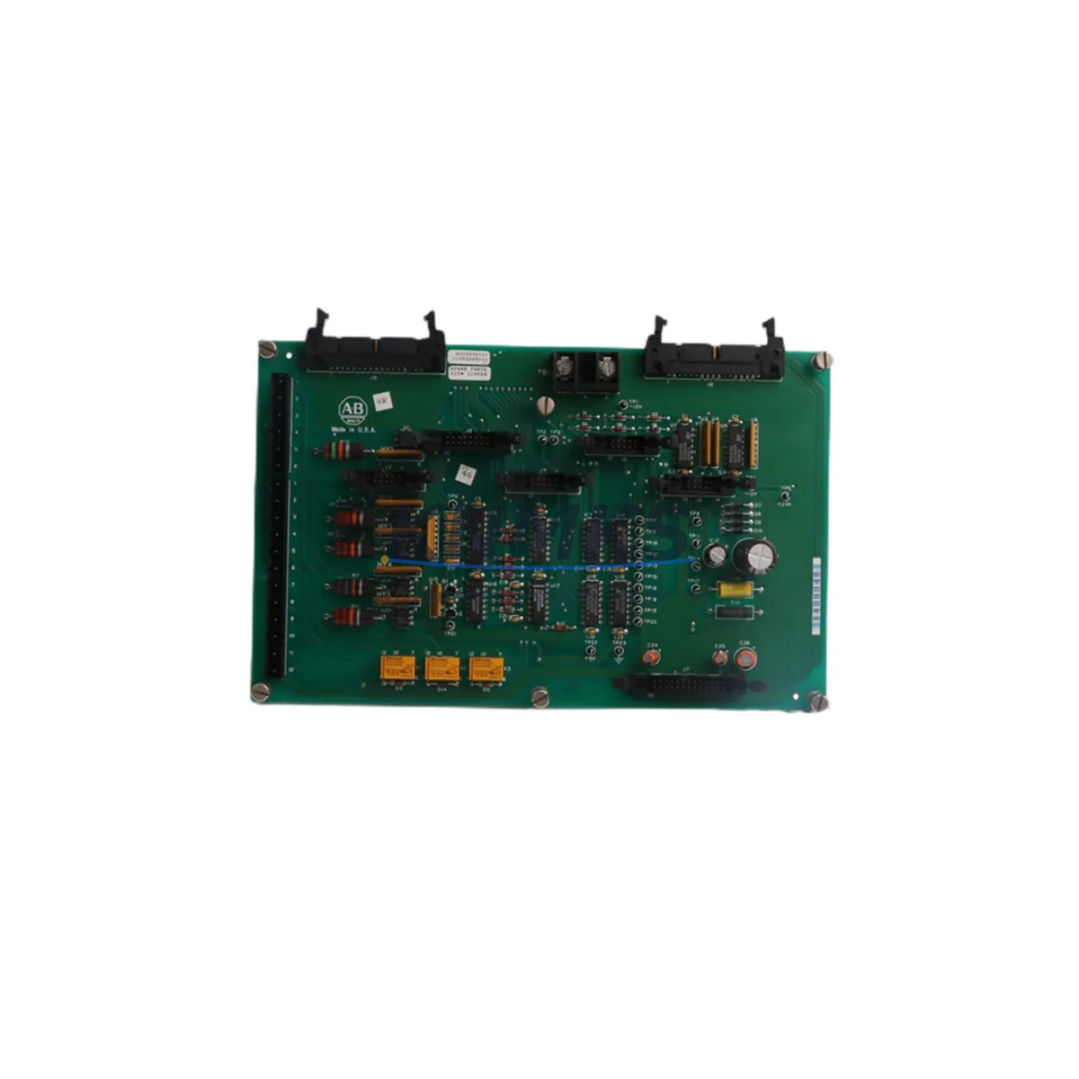
Allen-Bradley 119524 129708-01 Maintenance-Proven Spare Part for Factory Uptime
The Allen-Bradley 119524 129708-01 is a Power Stage Interface Board designed for the 1336 PLUS / 1336 PLUS II SPK series AC variable frequency drives. As a critical signal bridge between the drive’s control logic and its power conversion stage, this board governs gate firing signals, feedback loops, and fault detection routines that are fundamental to motor speed regulation and drive protection. In high-cycle manufacturing environments — including automotive assembly, material handling, HVAC systems, and process lines — the integrity of this interface board directly determines whether a drive recovers cleanly from a fault or escalates into an unplanned shutdown.
Maintenance engineers working with aging 1336 PLUS installations frequently encounter symptoms such as intermittent overcurrent faults, erratic speed response, gate drive errors, or complete drive lockout. In many cases, the root cause is traced to degraded signal paths or failed components on the power stage interface board rather than the power semiconductors themselves. Stocking the 119524 129708-01 as a verified spare eliminates the diagnostic ambiguity and allows field teams to execute a board-swap recovery within a single maintenance window — restoring production without waiting for depot repair or OEM lead times that can stretch weeks.
Each unit supplied by KNMKS is sourced from verified industrial channels, functionally tested prior to dispatch, and backed by a support terms confirmed by quotation. Our inventory is maintained to support both emergency replacement orders and planned annual overhaul procurement, ensuring your spare parts program remains responsive regardless of demand timing.
Spare Maintenance Table
| Parameter | Specification / Detail |
|---|---|
| Part Number | 119524 / 129708-01 |
| Brand | Allen-Bradley (Rockwell Automation) |
| Series | 1336 PLUS / 1336 PLUS II (SPK) |
| Product Type | Power Stage Interface Board (Drive Interface Board) |
| Function | Gate signal interface between control board and power stage; fault feedback, overcurrent detection |
| Compatible Drive Frames | 1336 PLUS SPK series (verify frame size against drive nameplate) |
| Mounting | Internal drive chassis, board-to-board connector and standoff mount |
| Operating Environment | Industrial panel / drive enclosure; standard drive ambient conditions |
| Origin | United States |
| Condition | Original spare — tested before shipment |
| Support terms | 12 Months from date of shipment |
| Lead Time | In-stock: ships within 1–3 business days |
| Maintenance Recommendation | Replace at first sign of gate fault, overcurrent trip, or erratic speed response; inspect annually during drive overhaul |
Maintenance Planning for Continuous Operation
Replacing the 119524 129708-01 interface board in isolation addresses the immediate fault, but a thorough maintenance strategy requires evaluating the surrounding drive and panel components that interact with this board during normal operation. Experienced maintenance engineers treat a drive interface board failure as a trigger for a broader system inspection — not a single-component swap.
Begin with the 1336 PLUS main control board (such as the 1336-BRF-SP2 or equivalent series control card), which generates the gate command signals that the 119524 129708-01 receives and translates. If the control board has been operating in a high-temperature or high-vibration environment, connector integrity and firmware revision should be verified before the replacement interface board is commissioned. Similarly, the 1336 PLUS power supply board that provides regulated DC rails to the interface and control circuitry should be checked for output voltage stability — a marginal power supply can cause intermittent interface board faults that are misdiagnosed as board failures.
The IGBT or SCR power module that the interface board drives is the next logical inspection point. Gate resistance, thermal paste condition, and module leakage current should be measured if the drive has logged repeated overcurrent or desaturation faults, as a degraded power module can stress the interface board over time. Alongside this, inspect the DC bus capacitor bank for capacitance loss and ESR drift — capacitor degradation creates voltage ripple that can corrupt gate timing signals and generate false fault conditions on the interface board.
For drives installed in control cabinets with multiple axes or shared bus configurations, also review the dynamic braking resistor and chopper module connections, the 24 VDC control power supply feeding the drive’s logic circuits, and any signal isolation modules used on analog speed reference or feedback wiring. Loose terminal connections on the I/O terminal block or degraded shielding on encoder or tachometer cables can introduce noise that manifests as interface board faults. Finally, confirm that any communication adapter cards (such as DeviceNet, ControlNet, or EtherNet/IP scanner modules) seated in the drive are firmly connected, as communication card faults can sometimes be misattributed to the power stage interface during initial diagnostics.
Building a cabinet-level spare kit that includes the 119524 129708-01 alongside a control board, a power supply board, and a set of DC bus fuses provides a complete first-response inventory that covers the majority of 1336 PLUS drive failure modes without requiring depot return.
Site Replacement Workflow
Step 1 — Fault Verification: Before ordering or installing a replacement 119524 129708-01, retrieve the drive’s fault history via the 1336 PLUS HIM (Human Interface Module) or through RSLogix / Studio 5000 if the drive is networked. Confirm that the logged fault codes point to gate drive, power stage, or interface communication errors rather than external wiring or load faults.
Step 2 — Safe Isolation: De-energize the drive following your site’s lockout/tagout procedure. Allow the DC bus to fully discharge (verify with a calibrated meter — typically wait a minimum of 5 minutes after power removal for 1336 PLUS drives). Do not handle the interface board until bus voltage is confirmed below 50 VDC.
Step 3 — Board Removal: Document the existing board’s connector positions and any jumper or DIP switch settings before removal. Photograph the installation if this is the first time the drive has been opened. Remove the board carefully, avoiding stress on the board-to-board connectors.
Step 4 — Inspection and Comparison: Compare the removed board against the replacement 119524 129708-01. Verify part number markings, revision level compatibility, and connector layout. Transfer any jumper settings from the original board to the replacement if applicable.
Step 5 — Installation and Commissioning: Seat the replacement board firmly, reconnect all connectors, and restore power. Clear the drive fault log and perform a no-load test run before reconnecting the motor load. Monitor the drive for the first 30 minutes of loaded operation and confirm that no gate or interface faults recur.
Step 6 — Documentation: Record the replacement date, part number, and drive serial number in your maintenance management system. Schedule the next inspection interval based on your site’s drive overhaul cycle — typically 12–24 months for high-duty-cycle applications.
Spare Parts Support FAQ
Q1: Is the 119524 129708-01 compatible with all 1336 PLUS drive frame sizes?
The 119524 129708-01 is associated with specific frame sizes within the 1336 PLUS SPK series. Compatibility depends on the drive’s horsepower rating and frame designation. Always cross-reference the drive nameplate and the original board part number before ordering. KNMKS can assist with compatibility verification — contact admin@knmks.com with your drive nameplate data.
Q2: How is each board tested before shipment?
Every 119524 129708-01 unit is functionally inspected prior to dispatch. Our process includes visual inspection for physical damage, connector integrity checks, and where applicable, powered functional verification. Units that do not pass inspection are not shipped. A support terms confirmed by quotation cover defects in materials and workmanship from the date of shipment.
Q3: What is the recommended inventory strategy for 1336 PLUS spare parts?
For facilities operating multiple 1336 PLUS drives, we recommend maintaining at least one interface board spare per drive family in your on-site inventory. For critical production lines with no redundant drive, consider holding two units. Pair the interface board spare with a control board and a set of DC bus fuses to cover the most common failure scenarios without a full drive replacement.
Q4: Can KNMKS support long-term supply for discontinued or hard-to-find Allen-Bradley parts?
Yes. KNMKS specializes in maintaining inventory of legacy and discontinued industrial automation components, including 1336 PLUS series parts that are no longer available through standard distribution channels. We support ongoing procurement programs for maintenance teams managing aging installed bases. Contact us at admin@knmks.com or +86 18359268345 to discuss long-term supply agreements.
© 2026 KNMKS. All rights reserved.
Original Source: https://knmks.com
Contact: admin@knmks.com | +86 18359268345
Product Identification
- Brand / Ecosystem
-
Allen-Bradley
Allen-Bradley - Model / Series
- 119524 129708-01
- Product Family
- PLCs & Controllers
- Availability Status
- Available on request after model and quantity confirmation
- Inquiry Type
- B2B RFQ, replacement inquiry and project spare-part request
- Pre-Quote Check
- Exact SKU, brand, series, quantity, nameplate photos and destination country are checked before quotation
System Path
Where this product fits in the KNMKS automation structure.
Specification & Inquiry Focus
- Control platform
- PLC, PAC and modular controllers
- Common needs
- CPU, rack, power and I/O expansion
- Project support
- Replacement, cabinet build and maintenance
Buyer Confirmation
Information KNMKS checks before replying.
- Exact model
- 119524 129708-01
- Brand / ecosystem
- Allen-Bradley
- Product family
- PLCs & Controllers
- Application note
- Replacement, maintenance, project build or spare-part list
- Useful photos
- Nameplate, installed unit, cabinet layout or connector side
- Delivery details
- Quantity, destination country and target schedule
Document Support
Files and notes can be confirmed during quotation.
- Product photos or nameplate confirmation when available
- Packing and delivery notes before quotation confirmation
- Support scope and delivery terms confirmed per inquiry
- Export document coordination for qualified B2B requests
Inquiry Support
- Model cross-checking before quotation
- CPU, power, rack and expansion module matching
- Support for replacement and project inquiry
What to Send Us
- Brand and exact model number: Allen-Bradley 119524 129708-01
- Quantity and required delivery time
- Application, replacement requirement or nameplate photo
- Destination country and shipping preference
RFQ Preparation
This is a product inquiry page built for RFQ communication.
Fast Model Check
Send this model to KNMKS for confirmation.
Include quantity, destination country and photos if this is a maintenance replacement. The inquiry will be saved with a reference number after submission.
Brand & Compatibility Note
KNMKS displays automation product information for well-known industrial brand ecosystems and compatible replacement references. Brand names are used for product identification and compatibility reference only; final availability and commercial terms are confirmed per quotation.
 Manufacturing
 Machine Tools
 Packaging
 Energy & Power
 HMI & Displays
 Servo Systems
 Variable Frequency Drives
 Sensors