
Overview
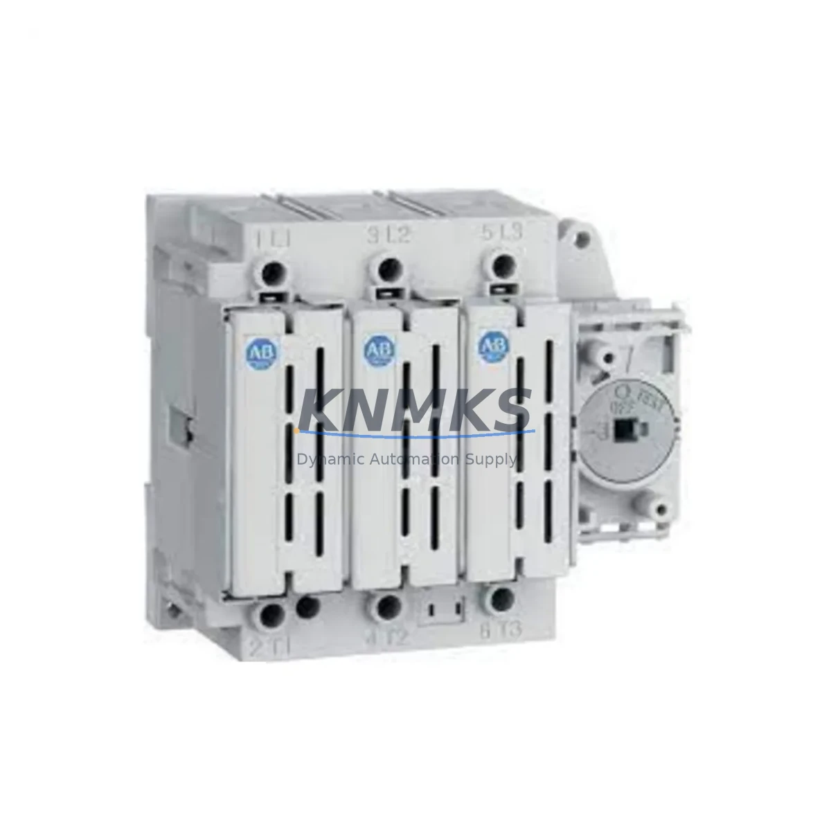
Allen-Bradley 194R-J400-1753 Migration-Ready Fusible Disconnect for Legacy Control Systems
The Allen-Bradley 194R-J400-1753 is a 30A, 600V fusible disconnect switch from the 194R TSC Series, engineered for direct integration into existing motor control centers, control cabinets, and legacy automation panels. As industrial facilities accelerate the retirement of aging Bulletin 194 and 194L series hardware, the 194R-J400-1753 has become a primary retrofit candidate — offering a verified upgrade path without requiring full panel redesign or PLC reprogramming.
For maintenance engineers and system integrators managing legacy control infrastructure, the 194R-J400-1753 delivers a reliable, code-compliant replacement that preserves existing terminal wiring layouts, DIN rail mounting footprints, and enclosure space allocations. Its compatibility with the 194R TSC Series means that facilities running older 194-series disconnects can execute a like-for-like swap with minimal downtime and no structural modifications to the control cabinet.
Before initiating a retrofit, engineers should verify the following against the existing installation: incoming power capacity and fuse sizing (30A maximum), terminal block pitch and wire gauge compatibility, available panel depth and width for the 194R form factor, module address assignments if the disconnect is monitored via a DeviceNet or EtherNet/IP node, and firmware revision of any associated PowerFlex drives or MicroLogix controllers that interface with the disconnect’s auxiliary contacts. In many legacy installations, the 194R-J400-1753 is installed alongside a 1492-SP series supplementary protector or a 1606-XLP power supply module — both of which should be inspected for compatibility during the same maintenance window.
When upgrading from discontinued 194L or 194E series disconnects, the 194R-J400-1753 requires confirmation that the existing HMI screen — typically a PanelView 800 or PanelView Plus 7 — does not reference legacy tag names tied to the old disconnect’s I/O map. If the control program was developed in RSLogix 500 or Studio 5000, a brief tag audit is recommended before commissioning the replacement unit. Communication links through a 1747-SDN DeviceNet Scanner or a 1756-ENBT EtherNet/IP bridge module should also be verified to ensure the new disconnect’s auxiliary contact signals are correctly mapped.
Migration Compatibility Table
| Parameter | 194R-J400-1753 Specification | Retrofit Notes |
|---|---|---|
| Rated Current | 30A | Verify upstream fuse sizing matches; replace if legacy fuse is undersized |
| Rated Voltage | 600V AC/DC | Compatible with standard 480V and 600V industrial panels |
| Series Compatibility | 194R TSC Series | Direct replacement for 194R TSC; verify handle and cover accessory fit |
| Mounting | DIN Rail / Panel Mount | Confirm rail type (EN 50022 35mm); check panel depth ≥ 60mm |
| Terminal Wiring | Screw terminal, standard pitch | Re-use existing wire ferrules; confirm torque spec (1.2–1.5 Nm) |
| Communication Interface | Auxiliary contact output | Map aux contacts to existing PLC I/O card (e.g., 1756-IB16 or 1769-IQ16) |
| Legacy Replacement | 194L / 194E Series | Tag audit required in RSLogix 500 / Studio 5000 before commissioning |
| Commissioning | On-site functional test | Verify open/close cycle, aux contact continuity, and interlock logic |
| Support terms | 12 Months | Covers manufacturing defects; includes pre-shipment functional test |
Retrofit Planning for Existing Automation Systems
A successful 194R-J400-1753 retrofit begins with a structured bill-of-materials review. In a typical motor control center upgrade, the disconnect is one of several components being replaced simultaneously. Engineers commonly source the following alongside the 194R-J400-1753: a 1492-SP1C supplementary protector for branch circuit protection, a 1606-XLP72E power supply module to support updated 24VDC control circuits, a 1769-IQ16 CompactLogix digital input module to capture the disconnect’s auxiliary contact status, and a 1747-L543 SLC 5/04 controller if the legacy CPU is also being retired in the same project phase.
For facilities migrating from older Modbus RTU-based control architectures to EtherNet/IP, the 194R-J400-1753’s auxiliary contacts can be wired directly into a 1734-AENT POINT I/O EtherNet/IP adapter, eliminating the need for a dedicated serial communication module. This approach reduces panel wiring complexity and supports remote monitoring through FactoryTalk View or equivalent SCADA platforms.
Installation space is a frequent constraint in legacy panel retrofits. The 194R-J400-1753’s compact 194R TSC form factor is designed to fit within the same cutout envelope as predecessor models, but engineers should confirm available depth behind the panel door and clearance for the operating handle mechanism. If the existing enclosure is a NEMA 12 or IP54-rated cabinet, verify that the new disconnect’s ingress protection rating is compatible with the environmental classification of the installation area.
Downtime Control During System Migration
Minimizing production downtime during a disconnect replacement requires a pre-staged swap strategy. Before the maintenance window opens, the replacement 194R-J400-1753 should be bench-tested for open/close operation, auxiliary contact continuity, and fuse holder integrity. All terminal labels should be photographed and documented against the existing wiring diagram before any conductors are removed.
To protect the original program logic, a full backup of the PLC project file should be exported from Studio 5000 or RSLogix 500 and stored offline before the panel is de-energized. If the control system includes a PanelView HMI, the application file should also be archived. During the swap, the existing wire ferrules and terminal markings should be preserved wherever possible to accelerate recommissioning.
Once the 194R-J400-1753 is installed and wired, a controlled energization sequence should be followed: verify incoming voltage at the line terminals, confirm fuse continuity, close the disconnect under no-load conditions, and then verify auxiliary contact signal propagation through the PLC I/O scan. Only after all interlock logic has been confirmed should the downstream motor load be re-energized. This sequence typically allows a complete swap to be completed within a two-hour planned maintenance window, preserving field control continuity and reducing the risk of unplanned production loss.
Retrofit Support FAQ
Q: Is the 194R-J400-1753 a direct replacement for the 194L-J400 series?
A: The 194R-J400-1753 is the recommended upgrade path for 194L and 194E series disconnects of equivalent amperage. While the electrical ratings are compatible, minor differences in handle accessory mounting and terminal block pitch may require adapter hardware. Confirm against your existing panel drawings before ordering.
Q: What pre-shipment testing is performed on each unit?
A: Each 194R-J400-1753 undergoes a functional open/close cycle test, auxiliary contact continuity verification, and insulation resistance check before dispatch. A test record is available upon request. All units ship with a support terms confirmed by quotation covering manufacturing defects.
Q: How do I verify firmware compatibility with my existing ControlLogix or CompactLogix system?
A: The 194R-J400-1753 does not contain embedded firmware — it is a hardwired disconnect switch. Firmware compatibility checks apply to any associated DeviceNet or EtherNet/IP communication adapter (e.g., 193-DNENCAT) used to monitor the disconnect’s status. Verify the adapter’s firmware revision against your controller’s EDS file library in RSLinx Classic or Studio 5000.
Q: What is the typical lead time and do you maintain stock?
A: We maintain ready inventory of the 194R-J400-1753 to support urgent retrofit and breakdown replacement scenarios. Standard orders ship within 1–3 business days. For large-quantity project orders, contact our sales team to confirm availability and arrange expedited dispatch.
© 2026 KNMKS. All rights reserved.
Original Source: https://knmks.com
Contact: admin@knmks.com | +86 18359268345
Product Identification
- Brand / Ecosystem
-
Allen-Bradley
Allen-Bradley - Model / Series
- 194R-J400-1753
- Product Family
- PLCs & Controllers
- Availability Status
- Available on request after model and quantity confirmation
- Inquiry Type
- B2B RFQ, replacement inquiry and project spare-part request
- Pre-Quote Check
- Exact SKU, brand, series, quantity, nameplate photos and destination country are checked before quotation
System Path
Where this product fits in the KNMKS automation structure.
Specification & Inquiry Focus
- Control platform
- PLC, PAC and modular controllers
- Common needs
- CPU, rack, power and I/O expansion
- Project support
- Replacement, cabinet build and maintenance
Buyer Confirmation
Information KNMKS checks before replying.
- Exact model
- 194R-J400-1753
- Brand / ecosystem
- Allen-Bradley
- Product family
- PLCs & Controllers
- Application note
- Replacement, maintenance, project build or spare-part list
- Useful photos
- Nameplate, installed unit, cabinet layout or connector side
- Delivery details
- Quantity, destination country and target schedule
Document Support
Files and notes can be confirmed during quotation.
- Product photos or nameplate confirmation when available
- Packing and delivery notes before quotation confirmation
- Support scope and delivery terms confirmed per inquiry
- Export document coordination for qualified B2B requests
Inquiry Support
- Model cross-checking before quotation
- CPU, power, rack and expansion module matching
- Support for replacement and project inquiry
What to Send Us
- Brand and exact model number: Allen-Bradley 194R-J400-1753
- Quantity and required delivery time
- Application, replacement requirement or nameplate photo
- Destination country and shipping preference
RFQ Preparation
This is a product inquiry page built for RFQ communication.
Fast Model Check
Send this model to KNMKS for confirmation.
Include quantity, destination country and photos if this is a maintenance replacement. The inquiry will be saved with a reference number after submission.
Brand & Compatibility Note
KNMKS displays automation product information for well-known industrial brand ecosystems and compatible replacement references. Brand names are used for product identification and compatibility reference only; final availability and commercial terms are confirmed per quotation.
 Manufacturing
 Machine Tools
 Packaging
 Energy & Power
 HMI & Displays
 Servo Systems
 Variable Frequency Drives
 Sensors