
Overview
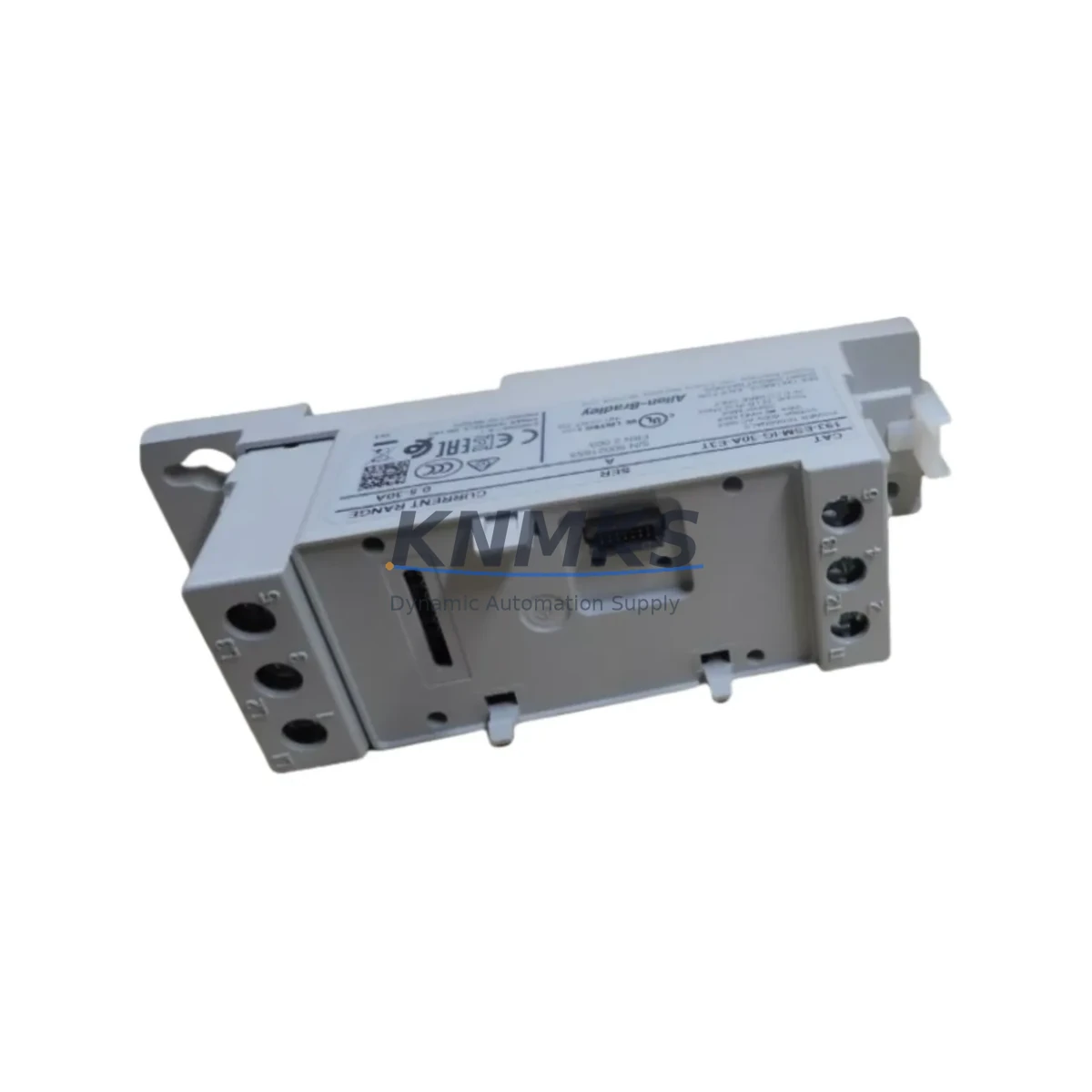
Allen-Bradley 193-ESM-IG-30A-E3T E3T Soft Starter Module: Legacy System Migration & Compatible Upgrade
The Allen-Bradley 193-ESM-IG-30A-E3T is a 30A electronic soft starter expansion module designed for the E3T Series overload relay platform. As legacy motor control centers and MCC buckets built around the E3 and E3 Plus overload relay family approach end-of-life, the 193-ESM-IG-30A-E3T has become a critical spare and retrofit component for engineers managing aging control infrastructure. Whether you are replacing a failed unit in a running production line, upgrading a legacy starter panel to meet current safety standards, or consolidating spare parts inventory ahead of a planned shutdown, this module provides a verified drop-in replacement path with minimal re-engineering.
Rated at 30A continuous current, the 193-ESM-IG-30A-E3T integrates directly with the E3T overload relay body, sharing the same DIN rail footprint and terminal block layout as earlier E3 and E3 Plus variants. The module supports DeviceNet communication, enabling seamless integration into existing Allen-Bradley DeviceNet networks without gateway hardware or protocol conversion. For plants running ControlLogix or CompactLogix controllers with a 1756-DNB or 1769-SDN DeviceNet scanner, the 193-ESM-IG-30A-E3T can be addressed and commissioned using the existing network configuration — preserving RSLogix 5000 or Studio 5000 program logic and eliminating the need for full I/O remapping.
Before installation, engineers should verify several key parameters to ensure a successful retrofit. Power supply capacity at the MCC bucket level must be confirmed, particularly if the replacement is part of a broader panel upgrade that adds monitoring or communication modules. Terminal wiring should be cross-referenced against the original E3 or E3 Plus wiring diagram, as pin assignments for the auxiliary output contacts and trip relay differ slightly between module generations. Backplane interface compatibility with the existing E3T relay body must be confirmed by checking the catalog suffix and firmware revision of the host relay. Module node address assignment on the DeviceNet segment should be documented before removal of the failed unit to avoid network address conflicts during recommissioning.
For facilities running older Bulletin 193 or Bulletin 592 overload relays alongside the E3T platform, the migration path typically involves replacing the overload relay assembly as a matched set — pairing the 193-ESM-IG-30A-E3T expansion module with a compatible 193-EECB or 193-EEGE E3T relay body. In applications where the existing motor branch circuit also includes a 140M motor circuit protector or a 100-C series IEC contactor, the soft starter module can be integrated without changes to the upstream protection device, provided the motor FLA and trip class settings are re-entered after module replacement. HMI screens built on PanelView Plus or PanelView 800 terminals that display E3T diagnostic data — including current imbalance, ground fault status, and thermal capacity — will continue to function without screen modification, as the DeviceNet data table structure is preserved across E3T module revisions.
Communication link integrity should be verified after installation using RSNetWorx for DeviceNet. Confirm that the 193-ESM-IG-30A-E3T appears on the network scan, that the EDS file matches the installed firmware version, and that all I/O connections are established before returning the motor branch to service. For installations where the DeviceNet trunk cable passes through the MCC section, verify that the drop cable length and network termination resistors remain within specification after any panel reconfiguration. Firmware version compatibility between the expansion module and the E3T relay body should be confirmed using the Rockwell Automation Product Compatibility and Download Center (PCDC) prior to installation.
Installation space confirmation is straightforward for standard MCC bucket retrofits: the 193-ESM-IG-30A-E3T uses the same physical envelope as the original E3T expansion module, requiring no additional panel depth or width. For custom-built control cabinets where the E3T assembly is mounted on a sub-panel rather than a standard MCC structure, verify that the DIN rail section is rated for the combined weight of the relay body and expansion module, and that adequate clearance exists for the DeviceNet drop cable connector.
Each 193-ESM-IG-30A-E3T unit shipped from our inventory undergoes pre-shipment functional verification, including communication interface check and output relay continuity test. Units are supplied with a support terms confirmed by quotation covering manufacturing defects and functional failures under normal operating conditions. Global shipping is available with lead times confirmed at order placement.
Migration Compatibility Table
| Parameter | 193-ESM-IG-30A-E3T | Notes / Retrofit Guidance |
|---|---|---|
| Rated Current | 30A | Confirm motor FLA ≤ 30A before replacement |
| Communication Protocol | DeviceNet | Compatible with 1756-DNB, 1769-SDN scanners; EDS file required |
| Host Relay Compatibility | E3T Series (193-EECB, 193-EEGE) | Verify relay body catalog suffix and firmware revision |
| Terminal Block Layout | Matches E3 / E3 Plus footprint | Cross-reference wiring diagram for auxiliary contact pin differences |
| DIN Rail Footprint | Standard E3T envelope | No additional panel space required for standard MCC retrofit |
| HMI Compatibility | PanelView Plus / PanelView 800 | DeviceNet data table structure preserved; no screen modification needed |
| Controller Compatibility | ControlLogix, CompactLogix | RSLogix 5000 / Studio 5000 program logic preserved |
| Upstream Protection | 140M MCP, 100-C IEC Contactor | No upstream device changes required; re-enter trip class settings |
| Firmware Verification | Via Rockwell PCDC | Confirm module-to-relay body firmware compatibility before installation |
| Pre-Shipment Test | Communication interface + relay continuity | Functional verification performed on every unit |
| Support terms | 12 Months | Covers manufacturing defects and functional failures under normal use |
Retrofit Planning for Existing Automation Systems
A successful retrofit of the 193-ESM-IG-30A-E3T into an existing motor control system requires coordinated planning across several component layers. The E3T expansion module does not operate in isolation — it functions as part of an integrated motor protection and communication assembly that typically includes the E3T relay body (such as the 193-EECB or 193-EEGE), a DeviceNet drop cable and micro-style connector, and the DeviceNet scanner module installed in the controller backplane.
For ControlLogix-based systems, the DeviceNet scanner is typically a 1756-DNB module installed in a 1756 chassis alongside the L6x or L7x controller. For CompactLogix systems, the 1769-SDN scanner occupies a slot in the local I/O bank. In either case, the scanner’s I/O connection to the 193-ESM-IG-30A-E3T must be re-established after module replacement, and the connection size and data format should be verified against the original EDS file configuration. If the plant’s RSNetWorx for DeviceNet configuration file is unavailable, the module can be re-commissioned using the EDS file downloaded from the Rockwell Automation support portal.
In MCC applications where multiple E3T assemblies are installed in adjacent buckets, the DeviceNet trunk cable runs through the MCC structure and connects to each bucket via a drop cable. When replacing a single 193-ESM-IG-30A-E3T in this configuration, the trunk cable and termination resistors should be inspected for damage or corrosion, particularly in older installations where the cable has been in service for more than ten years. A 1769-SDN or 1756-DNB network diagnostic scan can confirm network health before and after module replacement.
For plants that also operate Bulletin 592 or older Bulletin 193 overload relays in adjacent motor branches, the 193-ESM-IG-30A-E3T retrofit provides an opportunity to standardize the motor protection platform across the MCC. Pairing the new expansion module with a 193-EECB relay body and a 100-C series contactor creates a fully current-generation motor branch assembly that supports remote diagnostics, predictive maintenance data, and integration with FactoryTalk View or other SCADA platforms via the existing DeviceNet network.
Signal isolation requirements should also be reviewed during retrofit planning. In applications where the E3T trip output drives a safety relay or a hardwired interlock circuit, the auxiliary contact wiring from the 193-ESM-IG-30A-E3T should be verified against the original schematic before energizing the branch circuit. If the control circuit includes a 1492-IFM interface module for terminal block signal routing, confirm that the wiring assignments remain consistent with the replacement module’s contact configuration.
Downtime Control During System Migration
Minimizing production downtime during a 193-ESM-IG-30A-E3T replacement requires advance preparation and a structured commissioning sequence. The most effective approach is to pre-configure the replacement module’s DeviceNet node address before removing the failed unit from service. Node address assignment on the E3T expansion module is performed via the rotary switches on the module face; documenting the original address before removal eliminates one potential source of commissioning delay.
Program logic in the ControlLogix or CompactLogix controller does not require modification for a like-for-like module replacement, provided the DeviceNet node address and I/O connection size are preserved. The controller’s I/O tree will automatically re-establish communication with the replacement module once it is powered and connected to the DeviceNet network. If the controller is running in Run mode during the replacement, the DeviceNet scanner will generate a connection fault for the affected node; this fault clears automatically once the replacement module is online and the I/O connection is re-established.
To further reduce downtime risk, a pre-tested spare unit should be kept in inventory for each E3T expansion module installed in critical motor branches. Our inventory program supports blanket orders and reserved stock arrangements for customers managing large MCC installations with multiple 193-ESM-IG-30A-E3T units. Each spare unit is stored in anti-static packaging and maintained in a climate-controlled warehouse to preserve long-term reliability.
Field commissioning after module replacement should follow a structured sequence: power-on verification, DeviceNet network scan, I/O connection confirmation, motor protection parameter re-entry (FLA, trip class, ground fault threshold), and a no-load motor start test before returning the branch to full production load. This sequence can typically be completed in under 30 minutes by a qualified technician familiar with the E3T platform, keeping unplanned downtime to a minimum.
Retrofit Support FAQ
Q: Is the 193-ESM-IG-30A-E3T a direct replacement for earlier E3 and E3 Plus expansion modules?
A: The 193-ESM-IG-30A-E3T is designed for the E3T relay body platform. While it shares a similar physical footprint with earlier E3 and E3 Plus expansion modules, it is not electrically interchangeable with non-E3T relay bodies. Confirm that the host relay body carries the E3T designation (193-EECB or 193-EEGE) before ordering. If your existing installation uses an older E3 or E3 Plus relay body, a full relay assembly replacement may be required.
Q: What commissioning steps are required after replacing the module?
A: After physical installation, set the DeviceNet node address using the rotary switches, connect the DeviceNet drop cable, and power the MCC bucket. Use RSNetWorx for DeviceNet to confirm the module appears on the network scan and that the EDS file matches the installed firmware. Re-enter motor protection parameters (FLA, trip class, ground fault enable) via the DeviceNet interface or the E3T relay body keypad. Perform a no-load motor start test before returning to production.
Q: Can the existing DeviceNet wiring and connectors be reused?
A: In most cases, yes. The 193-ESM-IG-30A-E3T uses a standard micro-style DeviceNet connector compatible with existing drop cables. Inspect the connector and cable for damage or corrosion before reuse, particularly in installations where the cable has been in service for an extended period. If the drop cable shows signs of insulation damage or connector pin wear, replacement is recommended to avoid intermittent communication faults after commissioning.
Q: What does the support terms confirmed by quotation cover, and what is your stock availability?
A: Each 193-ESM-IG-30A-E3T unit is covered by a support terms confirmed by quotation from the date of shipment, covering manufacturing defects and functional failures under normal operating conditions. Physical damage, incorrect installation, or operation outside rated parameters is excluded. Stock is maintained in our warehouse and available for immediate shipment; lead time is confirmed at order placement. For customers requiring guaranteed availability for planned maintenance or MCC upgrade projects, reserved stock and blanket order arrangements are available — contact our sales team to discuss your requirements.
© 2026 KNMKS. All rights reserved.
Original Source: https://knmks.com
Contact: admin@knmks.com | +86 18359268345
Product Identification
- Brand / Ecosystem
-
Allen-Bradley
Allen-Bradley - Model / Series
- 193-ESM-IG-30A-E3T
- Product Family
- PLCs & Controllers
- Availability Status
- Available on request after model and quantity confirmation
- Inquiry Type
- B2B RFQ, replacement inquiry and project spare-part request
- Pre-Quote Check
- Exact SKU, brand, series, quantity, nameplate photos and destination country are checked before quotation
System Path
Where this product fits in the KNMKS automation structure.
Specification & Inquiry Focus
- Control platform
- PLC, PAC and modular controllers
- Common needs
- CPU, rack, power and I/O expansion
- Project support
- Replacement, cabinet build and maintenance
Buyer Confirmation
Information KNMKS checks before replying.
- Exact model
- 193-ESM-IG-30A-E3T
- Brand / ecosystem
- Allen-Bradley
- Product family
- PLCs & Controllers
- Application note
- Replacement, maintenance, project build or spare-part list
- Useful photos
- Nameplate, installed unit, cabinet layout or connector side
- Delivery details
- Quantity, destination country and target schedule
Document Support
Files and notes can be confirmed during quotation.
- Product photos or nameplate confirmation when available
- Packing and delivery notes before quotation confirmation
- Support scope and delivery terms confirmed per inquiry
- Export document coordination for qualified B2B requests
Inquiry Support
- Model cross-checking before quotation
- CPU, power, rack and expansion module matching
- Support for replacement and project inquiry
What to Send Us
- Brand and exact model number: Allen-Bradley 193-ESM-IG-30A-E3T
- Quantity and required delivery time
- Application, replacement requirement or nameplate photo
- Destination country and shipping preference
RFQ Preparation
This is a product inquiry page built for RFQ communication.
Fast Model Check
Send this model to KNMKS for confirmation.
Include quantity, destination country and photos if this is a maintenance replacement. The inquiry will be saved with a reference number after submission.
Brand & Compatibility Note
KNMKS displays automation product information for well-known industrial brand ecosystems and compatible replacement references. Brand names are used for product identification and compatibility reference only; final availability and commercial terms are confirmed per quotation.
 Manufacturing
 Machine Tools
 Packaging
 Energy & Power
 HMI & Displays
 Servo Systems
 Variable Frequency Drives
 Sensors