
Overview
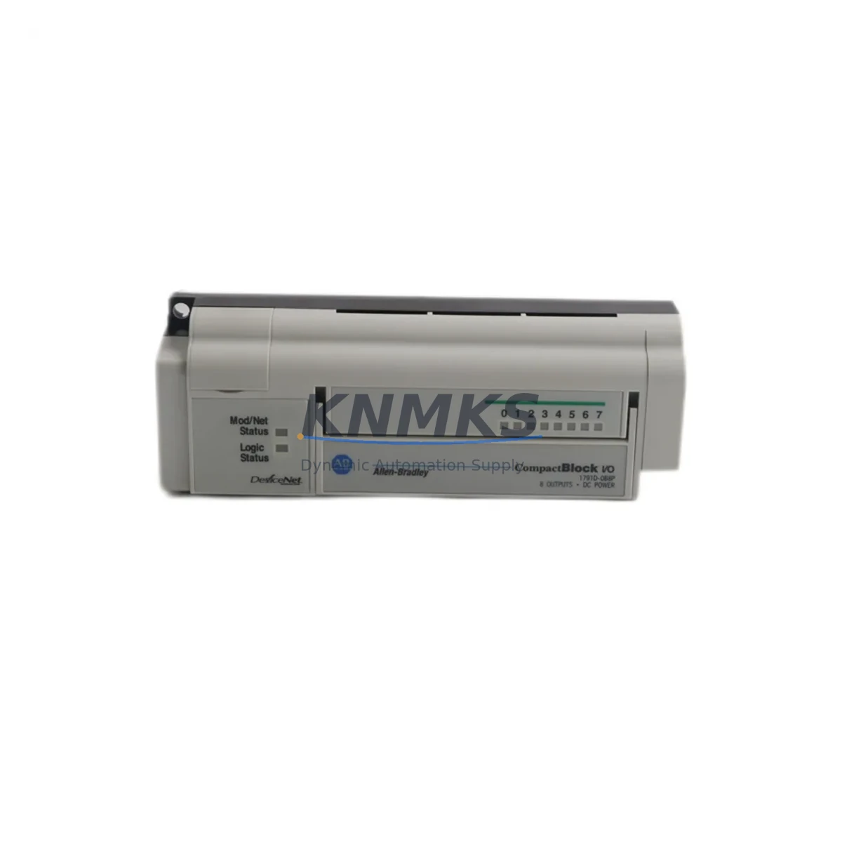
Allen-Bradley 1791D-0B8P Migration-Ready Digital Output Module for Legacy Control Systems
The Allen-Bradley 1791D-0B8P is an 8-point DeviceNet block I/O digital output module engineered for demanding industrial environments. Rated IP67 for dust and water ingress protection, this module is a proven solution for engineers undertaking legacy control system modernization, discontinued spare parts replacement, and DeviceNet network migration projects. Whether you are retrofitting an aging production line or restoring a control cabinet after a critical component failure, the 1791D-0B8P delivers the electrical and mechanical compatibility required to minimize engineering rework and reduce unplanned downtime.
As Rockwell Automation has progressively transitioned its distributed I/O portfolio toward EtherNet/IP-based architectures, many facilities operating original 1791D-series DeviceNet block I/O networks face increasing pressure to source reliable replacement modules. The 1791D-0B8P remains a critical stocking item for maintenance teams managing legacy lines where a full platform migration to 1732E ArmorBlock EtherNet/IP I/O is not yet feasible or cost-justified. For sites that must maintain DeviceNet continuity, this module provides a direct drop-in replacement path with no scanner reconfiguration required when node addressing and EDS file parameters are preserved.
Migration Compatibility Table
| Parameter | 1791D-0B8P Specification | Migration / Retrofit Notes |
|---|---|---|
| Network Protocol | DeviceNet (Group 2 Only Server) | Compatible with existing 1771-SDN, 1747-SDN, and 1756-DNB scanner modules; no protocol conversion required |
| Output Points | 8 x 24V DC sourcing outputs, 0.5A per point | Verify field device current draw; replace 1791D-0B8 (non-P) with attention to connector pinout differences |
| Installation | IP67 panel-mount, M12 connectors | Confirm mounting surface flatness and M12 port alignment; reuse existing cable assemblies if undamaged |
| Power Supply | 24V DC auxiliary power via M12 power connector | Validate auxiliary power capacity on 1606-XLP or equivalent 24V DC supply; add capacity if expanding I/O count |
| Node Address | Rotary switch, 0–63 | Record existing node address before removal; set identical address on replacement unit prior to installation |
| EDS File | Rockwell standard EDS | Re-use existing EDS in RSNetWorx for DeviceNet; re-commission module in online mode to verify I/O mapping |
| Firmware | Factory-loaded, no field update required | No firmware flashing needed; verify hardware revision matches original if scanner has revision-locked configuration |
| Communication Check | Module status LED + RSNetWorx diagnostics | Confirm green RUN LED and zero fault count in scanner I/O map after replacement |
| Support terms | support terms confirmed by quotation | Covered from date of shipment; includes DOA replacement and pre-shipment functional test |
Retrofit Planning for Existing Automation Systems
Successful integration of the 1791D-0B8P into an existing control cabinet begins with a thorough audit of the current DeviceNet segment. Engineers should document the 1756-DNB or 1747-SDN scanner’s I/O map, confirm available node addresses, and verify that the 24V DC auxiliary power supply — commonly a 1606-XLP series unit — has sufficient current headroom to support the replacement module alongside existing devices on the same segment.
Terminal and connector compatibility is a frequent source of delay during retrofit projects. The 1791D-0B8P uses standard M12 5-pin connectors for both network and power connections. If the existing cable assemblies are in good condition, they can typically be reused without modification. However, if the original installation used an earlier 1791D-0B8 variant without the sealed P-suffix housing, verify that the replacement module’s connector orientation matches the existing cable routing to avoid mechanical stress on field wiring.
For control cabinets that also house a 1791D-IB8 or 1791D-IB16 input module on the same DeviceNet drop, the replacement of the output module should be coordinated with a review of the entire drop’s health. Aging DeviceNet trunk cable, deteriorated T-port taps, or corroded termination resistors are common root causes of intermittent faults that are often misattributed to the I/O module itself. Replacing the 1791D-0B8P without addressing network infrastructure issues may result in recurring communication errors.
Where the retrofit scope extends to the PLC backplane, engineers working with a 1747 SLC 500 or 1756 ControlLogix platform should confirm that the DeviceNet scanner’s I/O table allocation for the 1791D-0B8P output module is correctly mapped in the ladder logic program. If the original program was developed in RSLogix 500 or RSLogix 5000, export and archive the current program before any hardware changes. This preserves the original output rung logic and allows rapid restoration if commissioning reveals unexpected behavior. For sites also managing a PanelView 600 or PanelView Plus HMI, verify that any output status indicators tied to the 1791D-0B8P’s bit addresses remain correctly mapped after the replacement module is commissioned.
Downtime Control During System Migration
Minimizing production downtime during a 1791D-0B8P replacement requires preparation before the maintenance window begins. The most effective approach is to pre-configure the replacement module offline: set the rotary node address switches to match the original unit, verify the module’s output wiring diagram against the existing M12 cable labels, and confirm the 24V DC power supply output voltage under load before the scheduled outage.
During the replacement window, the sequence should follow a structured isolation procedure: de-energize the auxiliary 24V DC power to the DeviceNet drop, disconnect the M12 network and power connectors, remove the original 1791D-0B8P, install the replacement unit, reconnect all connectors, and restore auxiliary power before bringing the DeviceNet scanner back online. This sequence protects the scanner’s communication buffer and prevents spurious fault entries in the PLC’s fault log.
After power restoration, use RSNetWorx for DeviceNet to perform an online scan of the network segment. Confirm that the replacement module appears at the correct node address with a healthy status. Cycle the PLC program from Program mode to Run mode and verify that all 8 output points respond correctly to commanded states. If the control system includes a safety relay or safety PLC monitoring the DeviceNet network health signal, confirm that the safety circuit resets cleanly before releasing the line to production. A pre-shipment functional test is performed on every 1791D-0B8P unit shipped from our inventory, reducing the risk of DOA failures and supporting a single-shift replacement window.
Retrofit Support FAQ
Q1: Is the 1791D-0B8P a direct replacement for the original 1791D-0B8?
The 1791D-0B8P is the sealed IP67 variant of the 1791D-0B8. Both modules share the same DeviceNet node configuration, EDS file, and output point count. The primary difference is the P-suffix sealed housing and connector style. Verify M12 connector compatibility with existing field cables before installation. In most retrofit scenarios, the 1791D-0B8P is a functional drop-in replacement with no scanner reconfiguration required.
Q2: What pre-shipment testing is performed on each unit?
Every 1791D-0B8P unit undergoes a functional output test and DeviceNet communication verification before shipment. Units are inspected for physical damage, connector integrity, and correct node address switch operation. A test report is available upon request for critical spare applications.
Q3: Can this module be used with a 1756 ControlLogix system?
Yes. The 1791D-0B8P is compatible with any DeviceNet scanner that supports Group 2 Only Server devices, including the 1756-DNB scanner module installed in a 1756 ControlLogix chassis. Configure the module in RSNetWorx for DeviceNet and map the output data to the appropriate controller tag in Studio 5000 Logix Designer.
Q4: What is the support terms coverage and lead time?
All 1791D-0B8P units are covered by a support terms confirmed by quotation from the date of shipment, including DOA replacement. Units are available from in-stock inventory and typically ship within 1–3 business days. Contact admin@knmks.com for current stock levels and expedited shipping options.
© 2026 KNMKS. All rights reserved.
Original Source: https://knmks.com
Contact: admin@knmks.com | +86 18359268345
Product Identification
- Brand / Ecosystem
-
Allen-Bradley
Allen-Bradley - Model / Series
- 1791D-0B8P
- Product Family
- PLCs & Controllers
- Availability Status
- Available on request after model and quantity confirmation
- Inquiry Type
- B2B RFQ, replacement inquiry and project spare-part request
- Pre-Quote Check
- Exact SKU, brand, series, quantity, nameplate photos and destination country are checked before quotation
System Path
Where this product fits in the KNMKS automation structure.
Specification & Inquiry Focus
- Control platform
- PLC, PAC and modular controllers
- Common needs
- CPU, rack, power and I/O expansion
- Project support
- Replacement, cabinet build and maintenance
Buyer Confirmation
Information KNMKS checks before replying.
- Exact model
- 1791D-0B8P
- Brand / ecosystem
- Allen-Bradley
- Product family
- PLCs & Controllers
- Application note
- Replacement, maintenance, project build or spare-part list
- Useful photos
- Nameplate, installed unit, cabinet layout or connector side
- Delivery details
- Quantity, destination country and target schedule
Document Support
Files and notes can be confirmed during quotation.
- Product photos or nameplate confirmation when available
- Packing and delivery notes before quotation confirmation
- Support scope and delivery terms confirmed per inquiry
- Export document coordination for qualified B2B requests
Inquiry Support
- Model cross-checking before quotation
- CPU, power, rack and expansion module matching
- Support for replacement and project inquiry
What to Send Us
- Brand and exact model number: Allen-Bradley 1791D-0B8P
- Quantity and required delivery time
- Application, replacement requirement or nameplate photo
- Destination country and shipping preference
RFQ Preparation
This is a product inquiry page built for RFQ communication.
Fast Model Check
Send this model to KNMKS for confirmation.
Include quantity, destination country and photos if this is a maintenance replacement. The inquiry will be saved with a reference number after submission.
Brand & Compatibility Note
KNMKS displays automation product information for well-known industrial brand ecosystems and compatible replacement references. Brand names are used for product identification and compatibility reference only; final availability and commercial terms are confirmed per quotation.
 Manufacturing
 Machine Tools
 Packaging
 Energy & Power
 HMI & Displays
 Servo Systems
 Variable Frequency Drives
 Sensors